
Building a custom 12V compressor fridge requires more than off-the-shelf components—it demands understanding the thermal load, selecting the right compressor for your cooling capacity, and integrating the refrigeration cycle into a compact, efficient system. Whether you’re an OEM developing a portable cooler product line or a DIY builder creating a custom van refrigeration setup, the compressor is the heart of your system.
This guide covers compressor selection, system design fundamentals, integration best practices, and real-world performance data for building reliable 12V refrigeration systems using miniature DC compressors.
Understanding 12V Compressor Fridge System Architecture
A 12V compressor fridge system consists of four primary components working in a closed refrigeration cycle. The compressor compresses refrigerant vapor from low pressure to high pressure, raising its temperature. The condenser coil rejects this heat to ambient air, condensing the refrigerant into liquid. An expansion device (capillary tube or thermostatic expansion valve) drops the pressure, causing the refrigerant temperature to plummet. The evaporator coil absorbs heat from the refrigerated space, evaporating the refrigerant back into vapor.
For mobile and battery-powered applications, every component must run on DC power. The compressor uses a brushless DC motor with variable-speed control. The condenser fan (if used) is a DC brushless design. The control board operates on 12V logic with integrated protections for undervoltage, overvoltage, overcurrent, and thermal limits.
System efficiency depends on proper component matching. An oversized compressor cycles frequently, reducing efficiency and component life. An undersized compressor runs continuously, unable to maintain setpoint temperature. Proper sizing requires calculating the thermal load: insulation R-value, surface area, temperature differential, and heat infiltration from door openings and ambient conditions.
Compressor Selection: Cooling Capacity and Power Requirements
Compressor selection starts with cooling capacity requirements. For a 40-60L portable fridge with moderate insulation (R-10) operating in 75-95°F ambient conditions, you need approximately 100-200W of cooling capacity at design conditions. For larger systems (80-120L) or higher ambient temperatures, 300-500W may be required.
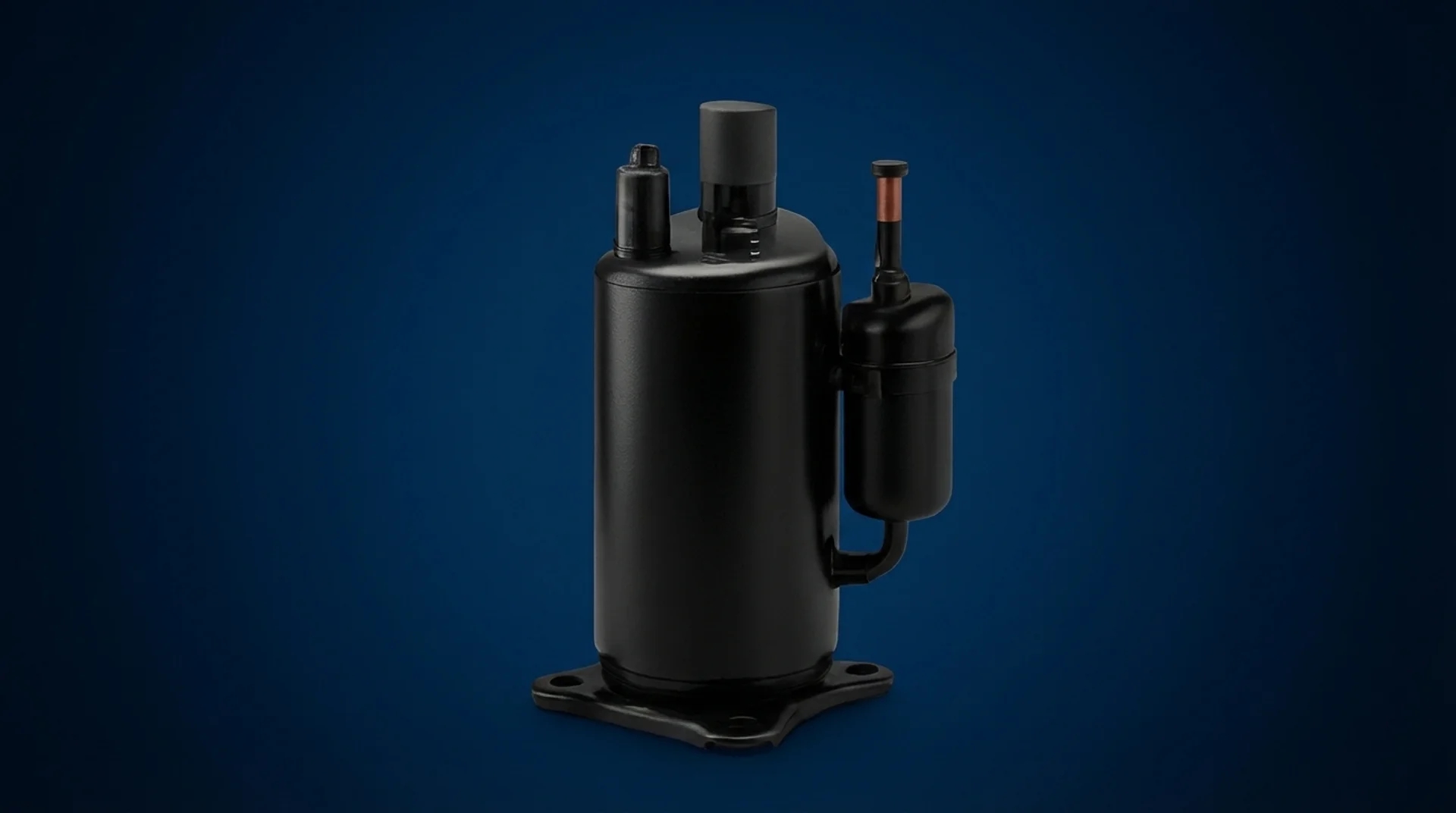
RIGID’s QX1901VDL miniature compressor delivers 100-455W cooling capacity at 12V DC, suitable for compact portable fridges, beverage coolers, and small refrigeration modules. The variable-speed motor (2,000-6,000 RPM) allows the compressor to modulate capacity based on thermal load, improving efficiency at partial load conditions. Physical dimensions are 56.5mm × 78mm (L×H) with a weight of 720g, enabling integration into space-constrained applications.
For larger capacity requirements, the XB075Z-12 delivers 850W (2,898 BTU) cooling capacity at 12V. This compressor suits 100-150L chest freezers, dual-zone fridge-freezer combinations, and commercial portable refrigeration. Weight is 7.8kg, requiring robust mounting and vibration isolation.
Both compressors use R134a refrigerant and operate across a wide voltage range (10.5-15.5V for 12V nominal), accommodating battery voltage fluctuations during discharge and charging cycles. The variable-speed drive board includes automatic protections: low-voltage cutoff at 10.5V, high-voltage cutoff at 15.5V, overcurrent protection, and thermal shutdown if motor temperature exceeds safe limits.
Thermal Load Calculation for Custom Fridge Design
Accurate thermal load calculation prevents undersizing or oversizing the compressor. The steady-state heat load consists of conduction through insulation, infiltration from door openings, and product load (cooling warm items to setpoint temperature).
Conduction load: Q = (k × A × ΔT) / thickness, where k is insulation thermal conductivity, A is surface area, ΔT is temperature difference between inside and outside, and thickness is insulation thickness. For polyurethane foam (k ≈ 0.022 W/m·K), 50mm thickness, 1.5 m² surface area, and 30°C temperature differential: Q ≈ 20W.
Infiltration load depends on door opening frequency and duration. Each opening exchanges cold air with warm ambient air. For a 50L fridge opened 10 times per day for 30 seconds each, infiltration adds approximately 15-25W average load in hot conditions.
Product load: cooling 5kg of food and beverages from 25°C to 5°C over 2 hours requires approximately 30W average power. This is a transient load that decreases once contents reach setpoint temperature.
Total design load: 20W (conduction) + 20W (infiltration) + 30W (product) = 70W. Add 30% safety margin for hot ambient conditions and aging insulation: 70W × 1.3 ≈ 90W. A compressor with 100-200W capacity provides comfortable margin.
For freezer applications (-18°C setpoint), the temperature differential increases from 30°C to 50°C (assuming 32°C ambient), increasing conduction load proportionally. Infiltration load also increases due to larger enthalpy difference. A freezer typically requires 1.5-2× the compressor capacity of an equivalent-volume fridge.
Refrigeration Cycle Design and Component Selection
Once the compressor is selected, the remaining components must be matched to the compressor’s capacity and operating conditions.
Condenser sizing: The condenser must reject the compressor’s cooling capacity plus the compressor’s power consumption (heat of compression). For a 150W cooling capacity compressor drawing 50W electrical power, the condenser must reject 200W. In 35°C ambient with natural convection, this requires approximately 0.15-0.2 m² of finned coil surface area. Forced convection with a fan reduces required area by 40-60%.
Evaporator sizing: The evaporator must absorb the design cooling load at the desired evaporating temperature. For a fridge application with 5°C setpoint, the evaporating temperature is typically -5 to 0°C. Lower evaporating temperature increases compressor work and reduces efficiency. Proper evaporator sizing (adequate surface area and airflow) allows higher evaporating temperature, improving system COP (coefficient of performance).
Expansion device: Capillary tubes are simple, reliable, and cost-effective for fixed-capacity systems. The tube length and diameter must be matched to the compressor capacity and refrigerant charge. Thermostatic expansion valves (TXV) provide better control and efficiency across varying load conditions but add cost and complexity. For variable-speed compressor systems, a properly sized capillary tube often provides adequate performance.
Refrigerant charge: Proper refrigerant charge is critical. Undercharge reduces capacity and can cause compressor overheating. Overcharge reduces efficiency and can cause liquid slugging (liquid refrigerant entering the compressor, damaging valves). Charge amount depends on system volume, component sizes, and operating conditions. For a small system with QX1901VDL compressor, typical charge is 80-150g of R134a. Charge must be determined experimentally during system commissioning.
Electrical Integration and Power Management
Proper electrical design ensures reliable operation and protects the compressor from voltage transients and overcurrent conditions.
Wire sizing: Use wire rated for the compressor’s maximum current draw with minimal voltage drop. The QX1901VDL draws up to 5A at maximum speed; use 14 AWG wire for runs up to 4 meters, 12 AWG for 4-8 meters. The XB075Z-12 draws up to 12A; use 10 AWG for runs up to 4 meters. Voltage drop should not exceed 3% (0.36V for 12V system) to prevent triggering the low-voltage cutoff.
Fusing: Install a fuse rated 125-150% of maximum current within 18 inches of the battery positive terminal. For QX1901VDL, use a 7.5A fuse. For XB075Z-12, use a 15A fuse. This protects the wiring in case of a short circuit.
Inrush current: Compressor startup draws 2-3× running current for 0.5-1 second. Ensure the power supply and battery can deliver this inrush without voltage sag below the low-voltage cutoff threshold. Lithium batteries handle inrush better than lead-acid due to lower internal resistance.
EMI filtering: Brushless DC motors generate electrical noise that can interfere with radios, GPS, and other electronics. The RIGID drive board includes basic EMI filtering, but additional filtering (ferrite beads on power leads, shielded cables) may be necessary in noise-sensitive applications.
Mechanical Integration and Vibration Isolation
Compressors generate vibration during operation. Proper mounting prevents vibration transmission to the cabinet structure and protects refrigerant lines from fatigue failure.
Mounting: Secure the compressor to a rigid mounting plate using rubber grommets or vibration isolators. The mounting plate should be bolted to the cabinet structure at multiple points to distribute loads. Avoid cantilevered mounting—the compressor should be supported on all sides.
Refrigerant line routing: Use flexible copper or aluminum tubing for refrigerant lines. Avoid sharp bends (minimum bend radius 3× tube diameter) and ensure lines have slack to accommodate vibration. Support lines every 15-20cm with cushioned clamps to prevent rubbing and fatigue. Do not route lines where they can contact sharp edges or moving parts.
Compressor orientation: The QX1901VDL can operate in any orientation, but horizontal mounting (compressor axis horizontal) is preferred for oil return. The XB075Z-12 should be mounted vertically (compressor axis vertical) per manufacturer specifications. Consult the compressor datasheet for orientation limits.
Vibration testing: After assembly, run the system at maximum speed and check for excessive vibration or noise. Resonance can occur if the compressor’s operating frequency matches a structural natural frequency. If resonance is detected, add damping material or change mounting stiffness to shift the natural frequency.
Control System Design and Temperature Management
The control system regulates compressor speed based on temperature feedback, manages defrost cycles (for freezer applications), and provides user interface and diagnostics.
Temperature sensing: Use a thermistor or digital temperature sensor (DS18B20) mounted inside the refrigerated space, away from the evaporator coil. The sensor should measure air temperature, not surface temperature. For accurate control, shield the sensor from direct airflow from the evaporator fan.
Control algorithm: A simple on-off thermostat cycles the compressor between full speed and off based on temperature setpoint and hysteresis band. This is adequate for fixed-speed compressors but causes temperature swings and reduces efficiency. For variable-speed compressors, a proportional control algorithm adjusts speed based on temperature error, maintaining tighter temperature control and improving efficiency.
Defrost control: Freezer applications require periodic defrost to remove ice buildup on the evaporator coil. Ice reduces airflow and heat transfer, degrading performance. Defrost can be passive (compressor off, allowing ambient heat to melt ice) or active (electric heater). Defrost frequency depends on ambient humidity and door opening frequency—typically every 6-12 hours for 15-30 minutes.
User interface: Minimum interface is a temperature setpoint adjustment and power switch. Advanced interfaces include digital temperature display, battery voltage monitoring, and fault code display. For OEM products, consider Bluetooth or Wi-Fi connectivity for remote monitoring and control via smartphone app.
System Testing and Performance Validation
After assembly, the system must be tested to verify performance, identify issues, and optimize efficiency.
Leak testing: Pressurize the system with dry nitrogen to 150-200 psi and hold for 24 hours. Pressure drop indicates a leak. Use soap solution or electronic leak detector to locate leaks. Common leak points: flare fittings, brazed joints, compressor shaft seal.
Vacuum and charging: Evacuate the system to below 500 microns using a vacuum pump. Hold vacuum for 1 hour to verify no leaks and remove moisture. Charge refrigerant by weight according to calculated charge amount. Monitor suction and discharge pressures during charging—proper charge results in 5-15°C superheat at the compressor suction port.
Pull-down test: Load the fridge with room-temperature water bottles (simulating product load) and measure time to reach setpoint temperature. Compare to calculated thermal load and compressor capacity. Excessive pull-down time indicates undersized compressor, insufficient airflow, or refrigerant charge issues.
Steady-state performance: After pull-down, measure compressor duty cycle (percentage of time running) in steady-state conditions. Duty cycle should be 30-60% in moderate ambient conditions. Higher duty cycle indicates undersized compressor or excessive heat load. Lower duty cycle indicates oversized compressor (acceptable but reduces efficiency).
Power consumption: Measure average power consumption over 24 hours in typical operating conditions. Compare to design calculations. For a 50L fridge with 100W compressor, expect 20-40Ah per day at 12V (240-480Wh) depending on ambient temperature and usage patterns.
Common Integration Challenges and Solutions
Several issues commonly arise during custom fridge integration. Understanding these challenges and their solutions accelerates development.
Insufficient cooling capacity: If the system cannot maintain setpoint temperature in hot ambient conditions, the compressor may be undersized, the condenser may have inadequate airflow, or the refrigerant charge may be low. Verify condenser fan operation, clean condenser coil, check refrigerant pressures, and recalculate thermal load. If the compressor is genuinely undersized, upgrade to a higher-capacity model.
Excessive power consumption: High power consumption indicates poor insulation, air leaks, oversized compressor cycling frequently, or low system efficiency. Check door seals, add insulation, verify refrigerant charge and superheat, and ensure evaporator and condenser coils are clean. Optimize control algorithm to reduce cycling.
Compressor short-cycling: Rapid on-off cycling (less than 3-minute run time) indicates oversized compressor, faulty thermostat, or refrigerant overcharge. Increase thermostat hysteresis, reduce refrigerant charge, or implement minimum run-time logic in the control system.
Noise and vibration: Excessive noise indicates loose mounting, refrigerant lines contacting structure, or compressor resonance. Tighten mounting hardware, reroute and secure refrigerant lines, add vibration damping material. If noise persists, the compressor may be defective.
Frost buildup on evaporator: In fridge applications (above-freezing setpoint), frost on the evaporator indicates excessive humidity, air leaks, or evaporator temperature below freezing. Improve door seals, reduce evaporator fan speed to raise evaporator temperature, or implement periodic fan-off cycles to allow frost to melt.
Sourcing Components for Custom Builds
Building a custom 12V compressor fridge requires sourcing the compressor, condenser and evaporator coils, expansion device, refrigerant, and control components.
RIGID miniature compressors are available for OEM integration and custom builds. The QX1901VDL and XB075Z-12 include the compressor, brushless DC motor, and variable-speed drive board as an integrated unit. Sample units and technical support are available for development projects. See our 12V compressor product line for specifications and ordering information.
Condenser and evaporator coils can be sourced from HVAC suppliers or custom-fabricated. For small systems, automotive AC evaporators and condensers can be adapted. Ensure coil capacity matches compressor capacity—undersized coils reduce efficiency and capacity.
Capillary tubes and TXVs are available from refrigeration suppliers. Capillary tube sizing requires trial and error—purchase several lengths and diameters for testing. TXVs must be matched to refrigerant type and capacity range.
Refrigerant (R134a) is available in small cans for DIY use or bulk cylinders for production. In many regions, refrigerant purchase and handling require certification. Ensure compliance with local regulations.
Control components (thermistors, relays, microcontrollers) are available from electronics distributors. For production, consider integrating control logic into a custom PCB. For prototyping, Arduino or Raspberry Pi can implement control algorithms.