
3D Printer Heater Cooler Systems: Solving Warping in High-Temperature Filaments
Anyone who has printed ABS, polycarbonate, or nylon on a desktop 3D printer knows the frustration: the first few layers adhere perfectly, but as the part grows, corners lift from the build plate, layers delaminate, and the finished piece warps into something that no longer matches the CAD model. The root cause is not the printer, the filament, or the slicer settings. It is thermal management — or more precisely, the lack of it.
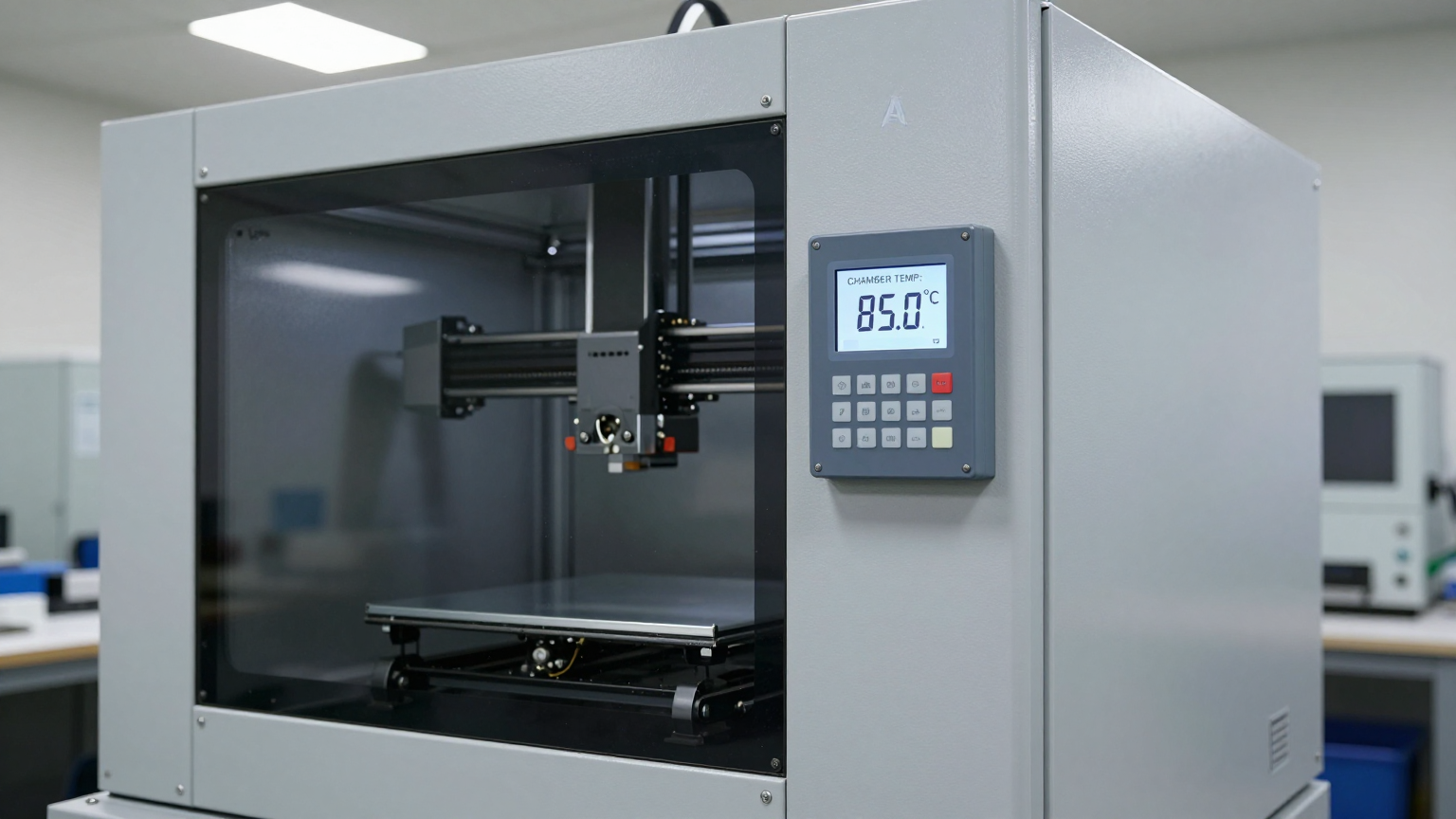
High-temperature engineering filaments require a controlled thermal environment throughout the entire print cycle. ABS needs a chamber temperature of 60–80°C to prevent differential cooling between layers. Polycarbonate performs best at 80–120°C. PEEK and ULTEM demand 120–180°C. At these temperatures, the material remains above its glass transition point during printing, allowing layers to bond properly and cool uniformly after the print completes. Without a heated chamber, the exposed surfaces of the part cool faster than the interior, creating internal stresses that manifest as warping, cracking, and layer separation.
A 3D printer heater cooler addresses this by maintaining precise chamber temperature during printing and then managing the controlled cooldown after the print completes — two distinct thermal phases that require opposite functions from the same system.
The Two-Phase Thermal Challenge in Industrial 3D Printing
Phase 1: Heated Chamber During Printing
During the print cycle, the chamber must maintain a stable elevated temperature. The heat sources are the heated bed (typically 80–110°C), the hot end (200–400°C depending on material), and any supplemental chamber heaters. The heat losses are through the chamber walls, the door seals, and any ventilation openings. In a well-insulated chamber, maintaining 60–80°C for ABS is relatively straightforward with resistive heaters alone.
But as target temperatures climb — 100°C for polycarbonate, 150°C+ for PEEK — the thermal management becomes more demanding. The electronics inside the chamber (stepper motors, wiring, sensors) have maximum operating temperatures that may be lower than the chamber setpoint. The print head cooling fan, essential for bridging and overhang quality, introduces cold air into the hot chamber. And the chamber temperature must remain uniform — a 10°C gradient across the build volume can cause differential shrinkage that warps large parts even in a heated enclosure.
Phase 2: Controlled Cooldown After Printing
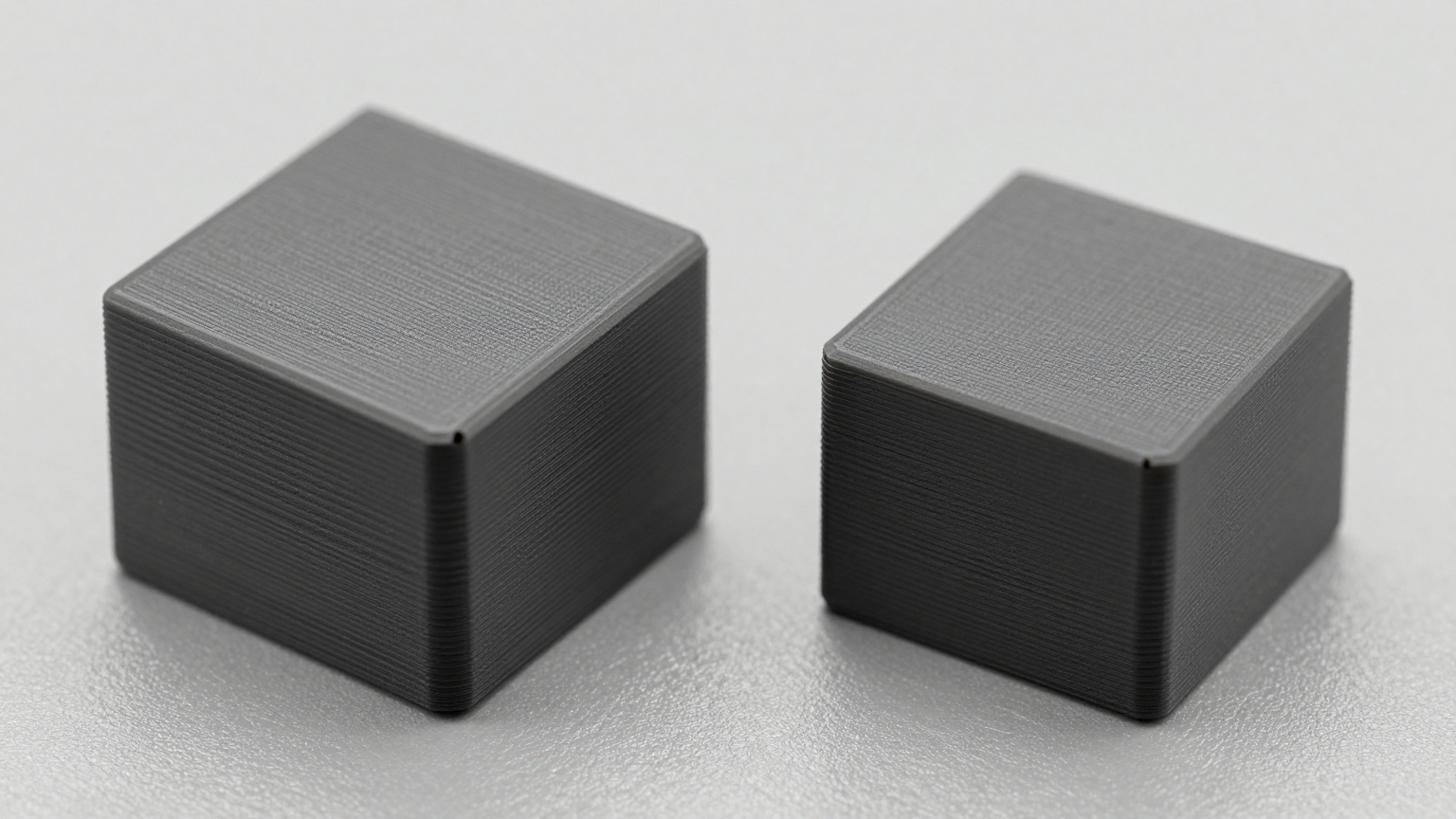
This phase is often overlooked but equally critical for part quality. When a print completes, the part must cool from chamber temperature to ambient. If this happens too quickly — opening the door immediately, or turning off the heater and letting the chamber cool passively — the rapid temperature change creates thermal shock. The outer surfaces of the part cool and contract while the interior is still warm and expanded. The result is the same warping and cracking that the heated chamber was designed to prevent.
The ideal cooldown profile is a controlled ramp — reducing chamber temperature at 1–2°C per minute, allowing the part to cool uniformly throughout its cross-section. For large, thick-walled parts in materials like polycarbonate or PEEK, this controlled cooldown can take several hours. A system that can only heat has no way to manage this ramp — it can only turn off the heater and let physics take over, which produces an uncontrolled, exponential decay curve rather than a linear ramp.
A 3D printer heater cooler that provides both active heating and active cooling enables precise control of both phases: maintaining the target temperature during printing and executing a programmed cooldown ramp after the print completes.
Why Resistive Heaters Alone Cannot Solve the Problem
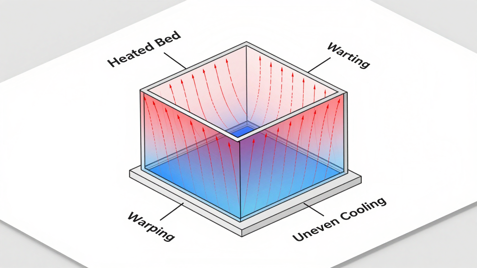
Most heated 3D printer chambers use resistive heating elements — PTC heaters, silicone heating pads, or nichrome wire elements. These work well for raising and maintaining chamber temperature. But they have three fundamental limitations:
No Active Cooling Capability
A resistive heater can only add heat. It cannot remove it. When the chamber temperature overshoots the setpoint — due to heat accumulation from the bed and hot end, or because the target temperature needs to decrease for the cooldown phase — the only option is to stop heating and wait for passive heat loss through the chamber walls. This is slow, uncontrolled, and produces temperature oscillations rather than stable regulation.
Poor Temperature Uniformity
Resistive heaters create hot spots near the heating element and cooler zones far from it. In a large chamber, the temperature difference between the heater side and the opposite wall can exceed 15°C. Forced air circulation (a fan inside the chamber) helps but does not eliminate the gradient, especially at higher temperatures where convective mixing is less effective relative to radiative heat transfer from the heater surface.
Energy Inefficiency at High Temperatures
Maintaining a chamber at 120°C in a 20°C ambient environment requires continuous power input to offset the 100°C temperature differential across the chamber walls. For a typical 500×500×500mm chamber with moderate insulation, this can require 300–500W of continuous heater power. Over a 12-hour print cycle, that is 3.6–6.0 kWh of energy consumed purely for thermal management.
Vapor-Compression Heat Pump: Heating, Cooling, and Efficiency in One System
A vapor-compression heat pump addresses all three limitations of resistive heating:
- Active cooling: The refrigeration cycle can remove heat from the chamber, enabling controlled cooldown ramps and preventing temperature overshoot during printing.
- Improved uniformity: The evaporator (in cooling mode) or condenser (in heating mode) distributes thermal energy through airflow across a heat exchanger, providing more uniform temperature distribution than a point-source resistive heater.
- Higher heating efficiency: In heating mode, the heat pump delivers COP values of 2.5–3.5, meaning each watt of electrical input produces 2.5–3.5 watts of heating. This reduces the continuous power draw for maintaining elevated chamber temperatures.
The bidirectional capability is particularly valuable for the print-to-cooldown transition. When the print completes, the system switches from heating mode to cooling mode and executes a programmed temperature ramp. The compressor speed adjusts continuously to maintain the target cooldown rate — faster if the chamber is cooling too slowly (due to residual heat from the bed), slower if it is cooling too quickly. The result is a smooth, linear cooldown profile that minimizes thermal stress in the finished part.
Integration Considerations for 3D Printer Enclosures
Adding a vapor-compression thermal management module to a 3D printer enclosure involves several practical design decisions:
Mounting and Airflow
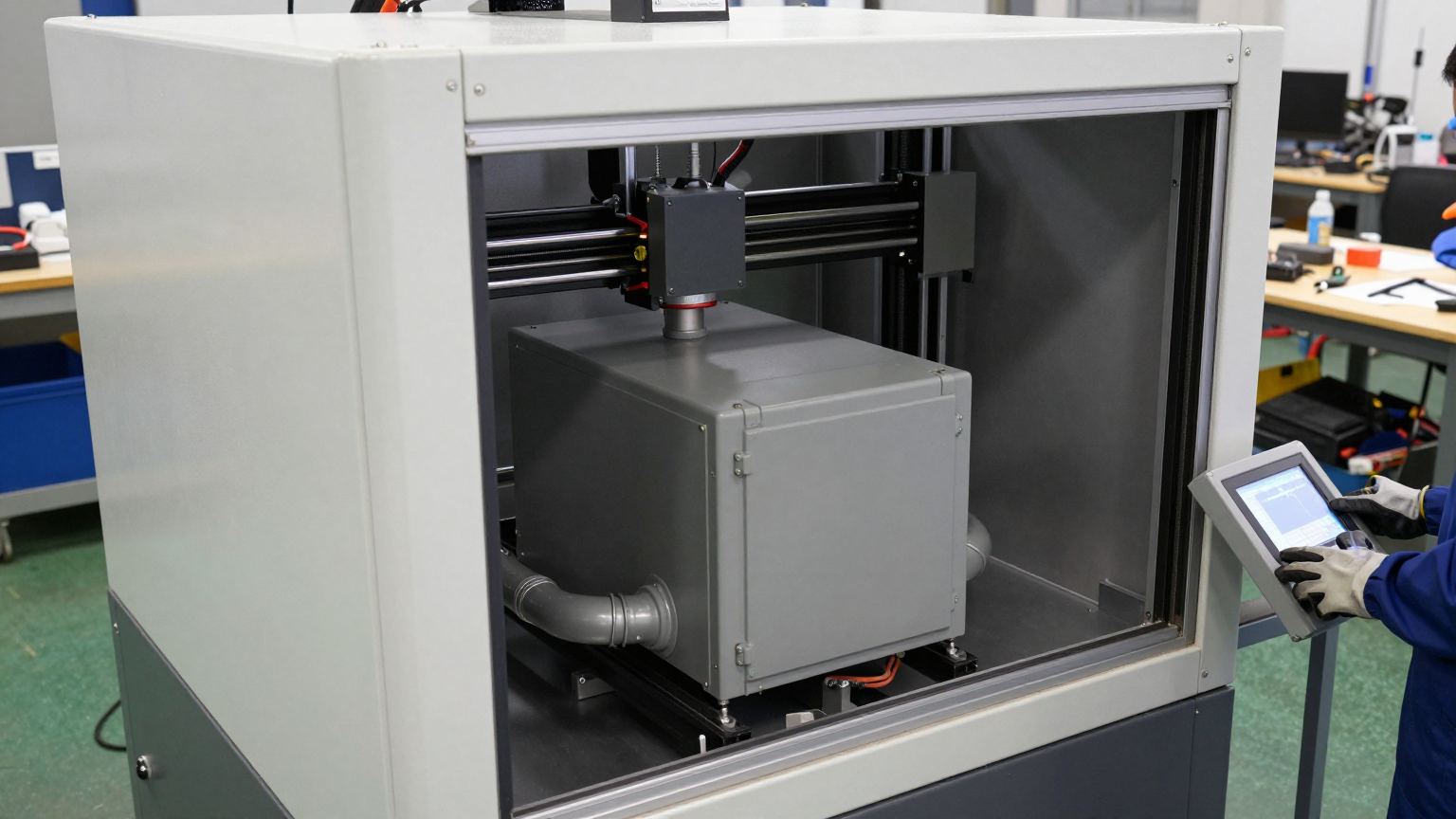
The cooling and heating module mounts on the exterior of the enclosure, with the evaporator/condenser heat exchanger ducted into the chamber interior. The external condenser (in cooling mode) or evaporator (in heating mode) rejects or absorbs heat from the room air. Internal airflow should be directed to avoid blowing directly on the print surface — which can cause localized cooling and layer adhesion issues — while still providing adequate circulation for temperature uniformity.
Temperature Range Compatibility
Standard R134a refrigerant systems operate effectively for chamber temperatures up to approximately 80–90°C, which covers ABS, ASA, and most nylon formulations. For higher-temperature materials like polycarbonate (100–120°C chamber) or PEEK (150°C+), the thermal module primarily handles the cooldown phase and supplemental temperature regulation, while resistive heaters provide the primary heating to reach the elevated setpoint. This hybrid approach — resistive heating for the high-temperature ramp, heat pump for regulation and cooldown — combines the strengths of both technologies.
Power and Voltage
A compact DC compressor module running on 24V or 48V integrates easily with the printer’s existing power supply infrastructure. Many industrial 3D printers already use 24V or 48V DC for stepper motors and heated beds. The thermal management module can share this power bus, simplifying wiring and eliminating the need for a separate AC power connection or inverter.
Control Interface
The compressor speed can be controlled via analog voltage (0–5V), PWM signal, or serial communication — all standard interfaces that integrate with common 3D printer control boards (Duet, Klipper, Marlin-based systems). This enables the printer firmware to manage chamber temperature as part of the print profile: set chamber temperature in the G-code, ramp to target before printing begins, maintain during printing, and execute a controlled cooldown after the print completes.
Material-Specific Chamber Temperature Guidelines
| Material | Recommended Chamber Temp | Cooldown Rate | Thermal Management Approach |
|---|---|---|---|
| PLA | Not required (ambient) | N/A | Active cooling may improve bridging |
| ABS / ASA | 60–80°C | 1–2°C/min | Heat pump handles full cycle |
| Nylon (PA6, PA12) | 60–80°C | 1°C/min | Heat pump handles full cycle |
| Polycarbonate | 100–120°C | 0.5–1°C/min | Hybrid: resistive heat + heat pump cooldown |
| PEEK / ULTEM | 150–180°C | 0.3–0.5°C/min | Hybrid: resistive heat + heat pump cooldown |
The controlled cooldown rate is as important as the chamber temperature itself. Faster cooldown rates increase internal stress and warping risk. Slower rates improve part quality but extend cycle time. The ability to program a specific cooldown rate — rather than accepting whatever passive cooling delivers — gives operators direct control over this quality-critical parameter.
Frequently Asked Questions
Does a 3D printer heater cooler replace the heated bed?
No. The heated bed provides localized adhesion heat at the build surface and remains essential for first-layer adhesion. The chamber thermal management system controls the ambient air temperature surrounding the part during and after printing. Both systems work together — the bed handles adhesion, the chamber handles volumetric temperature uniformity.
Can the system handle the fumes from ABS and other high-temperature materials?
The thermal management module circulates air through a sealed heat exchanger — the refrigerant circuit is completely isolated from the chamber air. This means chamber air (including any fumes or particulates) does not pass through the compressor or refrigerant lines. However, a separate filtration system (activated carbon or HEPA) is still recommended for fume management, as the thermal module is not designed for air purification.
How much does active cooling reduce the total print cycle time?
For materials requiring controlled cooldown (ABS, polycarbonate, PEEK), the cooldown phase can represent 20–40% of the total cycle time. Active cooling does not necessarily shorten this phase — the cooldown rate is set for part quality, not speed. However, active cooling ensures the cooldown follows the programmed rate precisely, preventing the extended tail of passive cooling where the last few degrees take disproportionately long. For production environments running multiple prints per day, this predictability improves scheduling and throughput.
What cooling capacity is needed for a typical 3D printer chamber?
For a 500×500×500mm chamber with moderate insulation, maintaining a 20°C differential (chamber at 80°C, ambient at 20°C with the heater off during cooldown) requires approximately 100–200W of active cooling capacity. A compact cool-and-heat module with 450–550W capacity provides ample headroom for faster cooldown rates or larger chambers.
Is vibration from the compressor a concern for print quality?
Miniature DC rotary compressors produce low vibration levels, and mounting the module on the exterior of the enclosure with anti-vibration grommets isolates it from the print structure. In practice, the vibration from stepper motors and the print head movement during printing is typically greater than the compressor vibration. During the cooldown phase (when the compressor is most active), the print head is stationary, so vibration has no effect on part quality.
From Warping to Precision: The Case for Active Chamber Thermal Management
Warping in high-temperature 3D printing is a solved problem — but only if the thermal management addresses both the heating and cooling phases of the print cycle. Resistive heaters handle the first phase well. The missing piece has been the second phase: controlled, active cooldown that prevents the thermal shock responsible for warping, cracking, and dimensional inaccuracy in engineering-grade prints.
A compact cool-and-heat module built around a variable-speed DC compressor provides both functions in a single, pre-charged unit that integrates with standard printer control interfaces. For production environments printing ABS, polycarbonate, nylon, or PEEK, this capability transforms the heated chamber from a simple enclosure into a precision thermal tool.
If your printer enclosure has specific constraints — unusual dimensions, high target temperatures, or integration with a particular control platform — we can review the thermal profile and discuss a configuration that fits your printing workflow and material requirements.