
Why Every Battery Heating System Fails the Same Way Below 10°C
Lithium-ion cells do not simply lose capacity in cold weather. They lose chemistry. Below roughly 10°C, the graphite anode can no longer intercalate lithium ions at the rate the charger delivers them. The surplus ions deposit as metallic lithium on the anode surface — a process called lithium plating. Once plating begins, it is irreversible: capacity drops, internal resistance climbs, and in severe cases dendrites puncture the separator, creating a thermal-runaway path.
The industry response has been to add heating. But heating alone is not the fix. The real question is how the battery heating system delivers thermal energy, how fast it reaches the safe-charge threshold, and whether it can sustain that threshold across a full charge cycle in sub-zero ambient conditions. Most field failures trace back to one of three root causes: insufficient heating power density, poor thermal uniformity across the pack, or a control loop that permits charging before cells have actually reached a safe temperature.
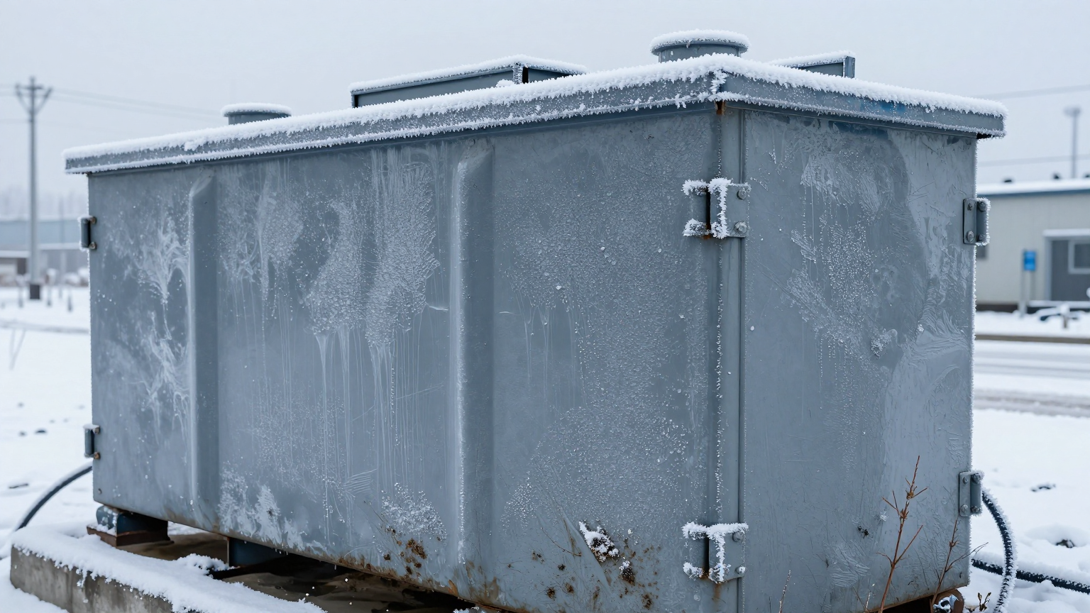
Failure Mode 1: PTC Heaters and the Surface-Temperature Trap
The most common battery heating system in small-to-mid-size packs uses PTC (Positive Temperature Coefficient) ceramic heaters bonded to the cell surface or sandwiched between module walls. PTC elements are self-regulating — their resistance rises with temperature, which limits peak power draw. That sounds like a safety feature, and it is. But it also means heating slows down precisely when you need it most: during the critical warm-up phase from −20°C to +10°C.
In field deployments, PTC-based systems often show a characteristic failure pattern. The BMS temperature sensor — typically mounted on the bus bar or module casing — reads 10°C and enables charging. But the cell core temperature may still be 5–8°C colder than the surface reading. The result: the BMS believes the pack is safe to charge while the anode is still in the plating zone. Over hundreds of cycles, this silent mismatch degrades capacity by 15–25% before anyone notices.
The root cause is not the PTC element itself. It is the combination of low COP (a coefficient of performance of 1.0 for resistive heating), slow ramp rate in extreme cold, and the thermal gradient between heater surface and cell core. In a 48V battery pack with 20 cells in series, the temperature spread across the pack can exceed 12°C during a PTC warm-up cycle — far beyond the 5°C uniformity target that most cell manufacturers specify.
Failure Mode 2: Heating Power Budget vs. Ambient Heat Loss
A battery enclosure is not a thermos. Even with 30mm polyurethane insulation, a typical 400×300×200mm battery box loses roughly 15–25W of thermal energy per degree Celsius of temperature difference between the pack and ambient air. At −20°C ambient with a 10°C target, that is 450–750W of continuous heat loss through the enclosure walls alone — before accounting for conduction through mounting brackets, cable penetrations, and the BMS board itself.
Many system designers size the heater for steady-state maintenance — keep the pack above 5°C — rather than for the cold-start ramp: bring the pack from −20°C to +10°C within 15 minutes. The result is a battery heating system that works in a mild winter but fails in the conditions that matter most. The pack sits in a slow warm-up loop, the vehicle or equipment cannot charge for 45–60 minutes, and operators override the BMS — either by jumping the relay or by reflashing the charge-enable threshold to a lower temperature.
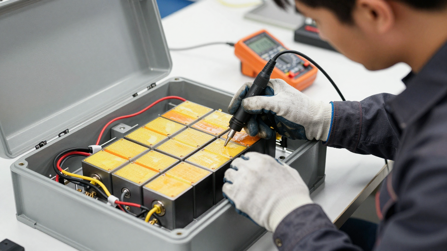 Both workarounds lead to the same outcome: accelerated lithium plating and premature pack replacement.
Failure Mode 3: No Cooling Path After Heating
This failure mode is less obvious but increasingly common in systems that operate across wide temperature swings — desert solar installations, outdoor EV charging stations, and mobile equipment that starts cold in the morning and runs hot by midday.
The pack heats to 10°C, charging begins, and internal heat generation from the charge current pushes cell temperatures upward. In a well-insulated enclosure designed to retain heat during warm-up, there is now no way to reject that heat. Cell temperatures overshoot to 40–45°C. The BMS may or may not flag this — many BMS designs have a generous high-temperature threshold of 55–60°C that allows prolonged operation in the degradation zone.
The underlying design flaw is treating heating and cooling as separate problems. A system that can only heat cannot manage the full thermal cycle. And a system that bolts on a separate cooling loop doubles the component count, the control complexity, and the failure surface.
Diagnostic Checklist: Is Your Pack Silently Plating?
Lithium plating does not announce itself with an alarm. It accumulates quietly over months. The following diagnostic sequence helps identify whether a battery heating system is contributing to plating risk:
Step 1: Check Thermal Gradient During Warm-Up
Place temperature probes on the cell surface closest to the heater and on the cell farthest from the heater. Log both during a cold-start warm-up cycle. If the delta exceeds 5°C when the BMS enables charging, the pack is at risk. This is the single most common finding in field audits of PTC-heated packs.
Step 2: Compare Charge-Enable Temperature vs. Actual Cell Core Temperature
Most BMS platforms log the temperature at which charging was enabled. Compare this against a thermocouple reading taken directly on the cell jelly-roll (if accessible) or between cells in the center of the module. A consistent offset of more than 3°C indicates the sensor placement is masking true cell temperature.
Step 3: Track Capacity Fade Rate
Healthy lithium cells in a well-managed thermal environment typically lose 2–3% capacity per year under moderate cycling. If your pack shows 5–8% fade in the first winter season, cold-charge damage is the likely cause — especially if the fade correlates with months where ambient temperatures regularly dropped below 0°C.
Step 4: Measure Warm-Up Time vs. Design Specification
Record the time from power-on to charge-enable at −10°C and −20°C ambient. If the actual warm-up time exceeds the design specification by more than 30%, the heater is undersized for the enclosure thermal losses, or insulation has degraded (moisture ingress is a common cause in outdoor installations).
Why Vapor-Compression Heat Pumps Change the Equation
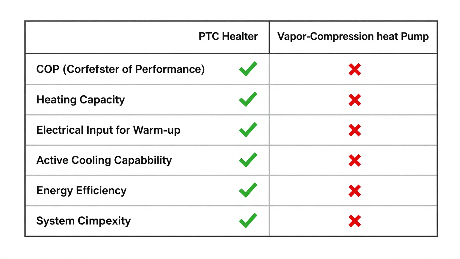
A vapor-compression heat pump does not generate heat by burning electricity through a resistor. It moves heat — extracting thermal energy from ambient air (even cold air contains usable energy down to roughly −15°C) and concentrating it into the battery enclosure. The thermodynamic advantage is substantial: where a PTC heater delivers 1W of heat per 1W of electrical input (COP = 1.0), a well-designed heat pump typically delivers 2.5–3.5W of heat per 1W of input, depending on ambient temperature and operating conditions.
For a battery heating system, this means three practical improvements:
- Faster warm-up: The same electrical power budget produces 2.5–3x more heating capacity, cutting cold-start ramp time significantly.
- Lower energy consumption: In battery-powered systems, every watt-hour spent on heating is a watt-hour not available for the primary load. A heat pump reduces the heating energy penalty proportionally to its COP advantage.
- Bidirectional capability: The same refrigeration circuit that heats the pack in winter can cool it in summer. One system, one set of components, one control loop — managing the full thermal cycle without the complexity of separate heating and cooling subsystems.
This bidirectional approach is particularly relevant for applications where the battery heating system must handle both extremes: cold-start preheating at dawn and active cooling during peak charge or discharge loads in the afternoon. A single compact cool-and-heat module replaces what would otherwise require a PTC heater, a separate cooling fan or liquid loop, and the associated wiring, relays, and control logic.
Sizing the Heating Capacity: A Practical Framework
The heating capacity required for a battery pack depends on four variables: enclosure surface area, insulation R-value, target temperature delta (ambient to charge-enable threshold), and acceptable warm-up time. A simplified approach:
Enclosure Heat Loss Estimation
Calculate the steady-state heat loss through the enclosure walls using the thermal conductance of the insulation material. For a 400×300×200mm enclosure with 25mm polyurethane foam (thermal conductivity approximately 0.025 W/m·K), the total surface area is roughly 0.52 m². At a 30°C temperature differential (−20°C ambient to +10°C internal), the steady-state loss is approximately 15–20W. This is the minimum continuous heating power needed just to maintain temperature — before any warm-up ramp.
Cold-Start Ramp Power
To warm the thermal mass of the cells themselves, add the energy required to raise the cell temperature. A typical 5 kWh lithium pack has a thermal mass of roughly 10–15 kJ/°C. Raising it 30°C in 15 minutes requires approximately 330–500W of net heating power delivered to the cells — on top of the enclosure losses. Total heating demand: 350–520W for a 15-minute cold start at −20°C.
With a PTC heater (COP = 1.0), this requires 350–520W of electrical input. With a vapor-compression heat pump operating at COP 2.5 in the same conditions, the electrical input drops to 140–210W. For a battery-powered system, that difference directly translates to preserved range or extended operational time.
Integration Considerations for Compact Battery Packs
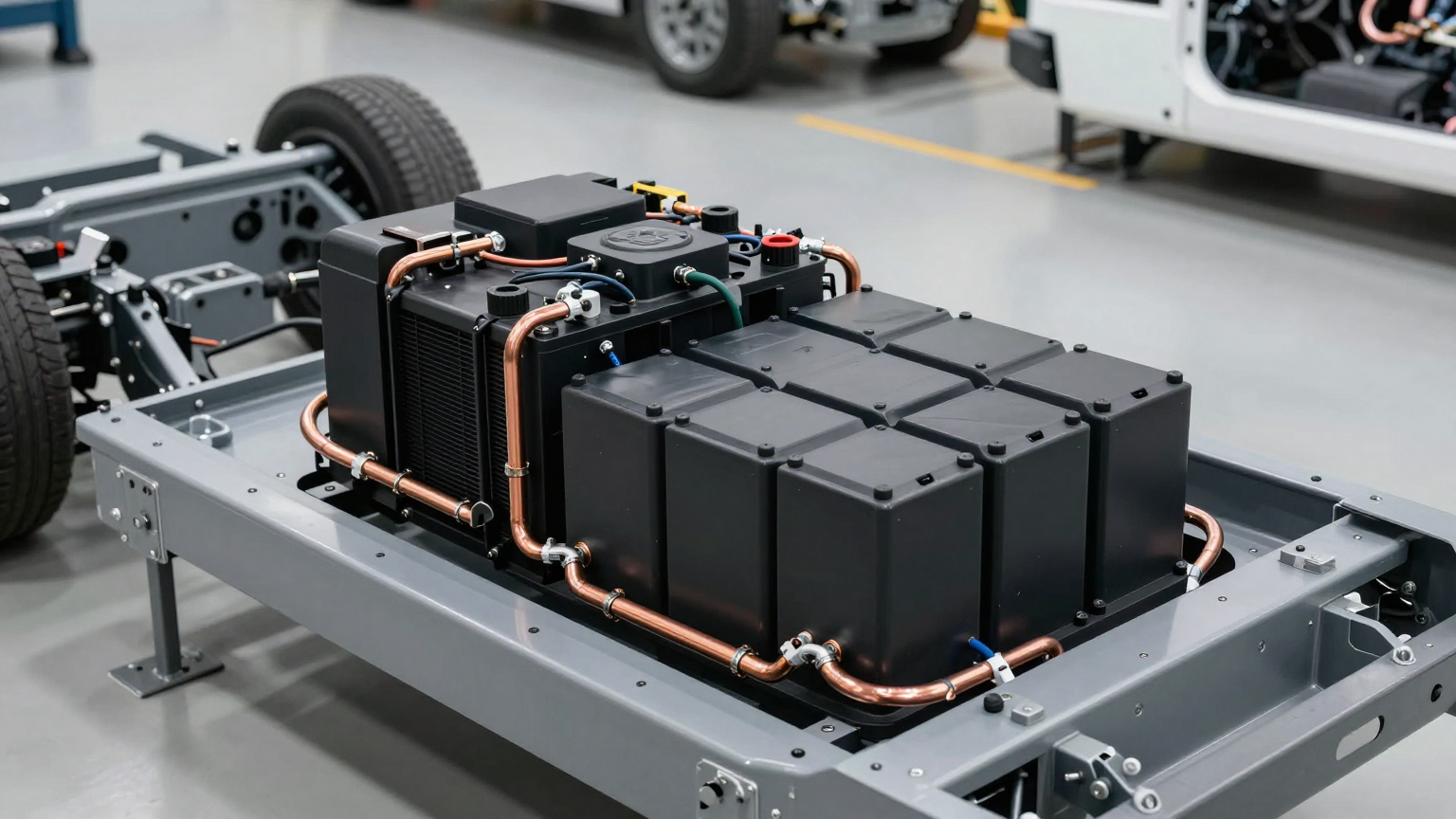
Fitting a vapor-compression thermal management system into a battery enclosure raises legitimate packaging concerns. Traditional HVAC heat pumps are designed for buildings, not for a space the size of a shoebox. The key enabler is the miniature DC compressor — a brushless DC rotary compressor small enough to mount directly on or adjacent to the battery module, running natively on the pack voltage (typically 24V or 48V DC) without an inverter.
A compact cool-and-heat unit built around such a compressor typically occupies a volume comparable to a paperback book. The refrigerant circuit is pre-charged at the factory, eliminating field brazing and vacuum procedures. The four-way reversing valve switches between heating and cooling modes under BMS control, and variable-speed compressor operation enables precise temperature regulation rather than simple on-off cycling.
For system integrators evaluating this approach, the critical integration parameters are:
- Voltage compatibility with the battery pack (DC-native operation avoids inverter losses)
- Condensate management in cooling mode (drain path or evaporation tray)
- Vibration isolation if the pack is in a mobile application
- Communication interface between the thermal unit and the BMS (typically analog 0–5V or PWM speed control)
Decision Framework: When to Upgrade from PTC to Active Thermal Management
Not every battery application needs a heat pump. For indoor-only systems in climate-controlled environments, a simple PTC heater with adequate BMS thresholds may be sufficient. The decision to move to vapor-compression thermal management typically depends on these factors:
| Decision Factor | PTC Heater May Suffice | Heat Pump Recommended |
|---|---|---|
| Operating environment | Indoor, climate-controlled | Outdoor, wide temperature swings |
| Minimum ambient temperature | Above −5°C | Below −10°C regularly |
| Cooling requirement | None or passive | Active cooling also needed |
| Power source | Grid-connected, unlimited | Battery-powered, energy-constrained |
| Pack value and lifecycle target | Low-cost, short lifecycle | High-value, long lifecycle expected |
| Charge frequency in cold | Occasional | Daily or continuous |
If two or more factors fall in the right column, the total cost of ownership typically favors an integrated thermal management approach over resistive heating — even accounting for the higher upfront component cost.
Frequently Asked Questions
Can lithium plating be reversed once it occurs?
In most practical scenarios, no. Some research suggests that very slow discharge cycles at elevated temperatures can partially reverse early-stage plating, but the capacity recovery is typically modest (1–3%) and the process is not reliable enough for field application. Prevention through proper thermal management is far more effective than attempted reversal.
What temperature should a BMS use as the charge-enable threshold?
Most cell manufacturers recommend a minimum of 0°C to 5°C for standard charge rates. However, this refers to the cell core temperature, not the surface or ambient reading. In practice, setting the BMS threshold at 10°C with a surface-mounted sensor provides a reasonable safety margin to account for the thermal gradient between sensor and cell core.
Does a heat pump work at very low ambient temperatures like −30°C?
Heat pump COP decreases as the temperature differential between source and sink increases. At −30°C ambient, a typical miniature heat pump may operate at COP 1.5–2.0 rather than the 2.5–3.5 seen at milder temperatures. This is still meaningfully better than PTC (COP 1.0), and the cooling capability in summer remains a significant advantage that PTC cannot provide.
How does a DC-native compressor differ from a standard AC compressor?
A DC-native compressor runs directly from a DC power source (12V, 24V, or 48V) using a brushless DC motor with an integrated inverter driver. This eliminates the need for a separate DC-to-AC inverter, which typically wastes 15–20% of input power as conversion losses. For battery-powered systems, DC-native operation preserves that energy for the primary application.
What is the typical lifespan of a miniature vapor-compression unit in continuous BTMS duty?
Lifespan depends on operating conditions, but well-designed miniature DC compressors in industrial applications typically operate for tens of thousands of hours. Variable-speed operation (rather than constant on-off cycling) reduces mechanical stress and extends service life. The pre-charged refrigerant circuit eliminates field connections that could develop leaks over time.
Can the same unit handle both battery preheating and cabin or enclosure cooling?
In many system architectures, yes. The thermal output of a compact cool-and-heat unit can be directed to the battery pack, to an air-cooled enclosure, or split between both — depending on ductwork and valve configuration. This flexibility is one of the primary advantages of a reversible vapor-compression system over dedicated single-function components.
Moving from Reactive Heating to Proactive Thermal Management
The pattern across all three failure modes is the same: a battery heating system designed as an afterthought — bolted on to meet a minimum specification — rather than integrated as a core subsystem from the start. Lithium plating is not a random failure. It is a predictable consequence of thermal design gaps that compound over every cold-weather charge cycle.
The shift from resistive heating to vapor-compression thermal management is not about adding complexity. It is about reducing it — replacing separate heating and cooling subsystems with a single, bidirectional, DC-native module that manages the full thermal envelope. For battery packs that operate outdoors, charge in cold conditions, or need to maintain precise temperature control across seasons, this approach typically delivers lower energy consumption, longer pack life, and fewer field failures.
If your current thermal architecture relies on PTC heating alone and you are seeing unexplained capacity fade after cold-weather seasons, the diagnostic checklist above is a practical starting point. If your constraints differ from the scenarios described here — different pack geometry, voltage, or ambient range — we can review the thermal requirements and align on a configuration path that fits your specific integration envelope.