
Chiller Anti-Siphon Protection Must Cover the Stopped Loop
Chiller anti-siphon protection should be selected from the paths coolant can follow after circulation stops. When equipment sits above a chiller with a vented reservoir, liquid may return through the supply, the return or a connected branch. A check valve in one line does not establish protection of the complete installation. Identify the actual reservoir arrangement and the stopped condition before choosing hardware.
For a negative-temperature RIGID MiniCool installation, the useful purchasing question is whether the proposed package can manage the elevated equipment in operation, shutdown and loss of power. This guide reviews those configuration requirements. It does not establish that MiniCool includes an anti-siphon option or prescribe an external valve retrofit.
Draw Both Liquid Paths Before Evaluating a Valve
Mark the chiller reservoir, supply connection, load passages and return connection on a simple installation drawing. Add the elevations and any secondary branches. The drawing should identify where the system is open to the atmosphere and which parts remain filled when the pump stops. A line labeled closed loop can still communicate with a vented tank.
Follow each possible return path independently. A valve preventing reverse flow in the supply line may leave the normal return path available. A bypass or auxiliary instrument can provide another route. The purpose is to describe the installation to the equipment supplier, rather than assuming that one product label answers every path question.
Evaluate the complete liquid path, not one isolated valve. Record the direction in which each proposed component passes or blocks liquid, together with the operating state that produces that behavior. Keep service valves identifiable separately from automatically operated protection.
Confirm Which Reservoir Arrangement the Chiller Actually Uses
A vented tank and a pressurized sealed circuit have different boundaries. In a vented arrangement, returning liquid can raise the reservoir level until the available space is used. A sealed system requires its own pressure and expansion review. Do not apply an explanation written for an open tank without confirming the actual MiniCool configuration.
Ask the supplier for the current fluid schematic and installation requirements. Establish the permitted external equipment elevation, reservoir operating levels and any restrictions on external valves. Photographs of a cabinet or its fill opening cannot establish the internal plumbing or the amount of usable reserve volume.
A reservoir intended to accept a defined return volume may need a different solution from one that must prevent that return. The inquiry should state which outcome is required. More than one acceptable architecture can exist, provided the complete installation and its operating states have been assessed.
Separate Drain-Back Volume From Temperature Expansion
Liquid returning from elevated equipment and liquid changing volume with temperature are separate contributions. They can occur during the same shutdown, but their causes and time scales differ. The existing discussion of sub-zero reservoir level changes explains the broader temperature-related behavior. Here, the additional task is to specify what the external installation can return.
As a hypothetical volume inventory, suppose the equipment can release 0.6 L and the connected hoses contribute another 0.4 L under the reviewed stopped condition. That is 1.0 L of possible return before considering thermal expansion, the initial reservoir level or other connected branches. These are illustrative inputs, not MiniCool reservoir specifications.
Do not count the same available space twice. A reserve allocated to warming coolant may not also be available for the entire returning external volume. Ask the supplier to review the combined level envelope at the relevant temperature and operating state.

Compare Protection Functions Without Copying Another Chiller
Chiller anti-siphon protection can involve coordinated components on more than one line. One manufacturer’s arrangement may combine a supply-side nonreturn function with a controlled return closure. That illustrates why both paths matter; it does not make the same arrangement suitable for a different pump, reservoir or controller.
| Function under review | Question for the supplied configuration | Important limit |
|---|---|---|
| Supply nonreturn function | Which reverse-flow path does it block? | Does not establish closure of another line. |
| Controlled return closure | What closes it, and in which operating states? | A powered-state description omits shutdown behavior. |
| Reservoir acceptance | What return volume can the installation accommodate? | Tank size alone does not define usable reserve. |
| Manual isolation | Who operates it and during which procedure? | Operator action is different from automatic protection. |
Compare proposals by the function delivered and its documented conditions. A collection of separately rated components is not yet evidence that their combined arrangement supports the installed chiller and load.
Specify Shutdown and Power-Loss States Separately
An ordinary stop command may leave control power available. A loss of incoming power may remove it. A local controller stop, host stop and service isolation can therefore place the liquid system in different states. Chiller anti-siphon protection should identify which of those conditions the proposal covers.
Request the valve positions and pump state for each relevant condition. Include what happens if a control signal is missing while the electrical supply remains present. Do not infer the unpowered position of a valve from its normal running position or from a generic description such as automatic.
Define the required stopped state explicitly. The supplier should explain how the proposed hardware reaches it and any conditions that prevent that outcome. This is a functional requirement, not an instruction to interrupt power to a customer’s sensitive experiment.
Account for the Extra Pressure Drop During Normal Circulation
A component added to control stopped flow also becomes part of the running circuit. Review its pressure drop at the intended flow and with the actual coolant. Available pump performance must be compared with the complete route, including hoses, load passages and the proposed protection components.
A low-temperature fluid can behave differently from water at room temperature. Obtain the applicable fluid properties and component information instead of choosing a valve solely from its connection diameter. Neither the pump’s free-flow figure nor a valve’s maximum pressure rating establishes the installed circulation rate.
The guide to liquid chiller loop pressure drop covers the broader hydraulic selection. The specific addition here is to verify that a stopped-flow solution does not leave the elevated load short of circulation while the system runs.
Review Restart as a Distinct Operating Condition
After a stop, the external circuit may have retained liquid, admitted air or partially emptied, depending on its design. Restart requirements follow that actual state. Ask how the approved configuration establishes circulation again and what evidence confirms flow through the load before normal operation resumes.
Valve opening and pump operation may need coordination defined by the equipment supplier. Opening too late, closing unexpectedly or leaving a line blocked can change the pump’s operating condition. Do not invent a universal delay or assume that a temperature display proves the external circuit has refilled.
Keep restart verification separate from reaching setpoint. The chiller can indicate a cold internal measurement while an elevated branch remains inadequately circulated. The acceptance plan needs evidence relevant to that branch, obtained through the approved equipment method.
Keep Trapped-Liquid and Service Conditions in the Review
Closing both lines can create an isolated liquid volume. If its temperature changes, its pressure behavior needs assessment. A protective arrangement should therefore be reviewed as part of the complete fluid system, including any required expansion accommodation and component pressure limits. This article does not specify a relief setting or an improvised bypass.
Service can also change the hydraulic state. A disconnected hose, drained instrument or manually closed isolation valve may invalidate the assumptions used for normal shutdown. Document the permitted service condition and the supplier’s return-to-operation procedure rather than treating every stopped state as equivalent.
Preserve access to the components that require inspection or maintenance. A configuration that works during commissioning can become difficult to verify after the equipment is moved against a wall. Include service access and clear component identification in the installation review.
Equipment relocation deserves another check. Moving the instrument to a higher shelf, adding a second elevated branch or replacing a short hose with a longer route can change the return inventory and the relevant stopped paths. Preserve actual elevations and hose identification with the accepted drawing. A previous result for the same chiller model does not automatically cover a rearranged laboratory installation. Ask whether the revised route remains within the supplier’s installation limits before relying on the earlier shutdown assessment.
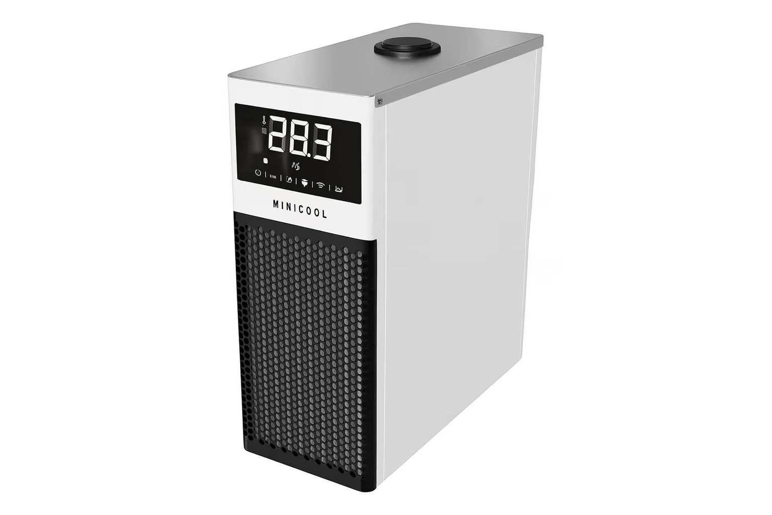
Place MiniCool Within Its Published Product Scope
The RIGID MiniCool family publishes a −40°C to 0°C cooling range. Chiller anti-siphon protection does not extend that range or establish available capacity at a particular negative setpoint. Match the thermal duty and the installed liquid arrangement as separate, connected selection tasks.
MiniCool’s pump curve, reservoir reserve, internal fluid schematic and supported anti-siphon hardware have not been established here for the ordered configuration. Request those details where they govern the installation. A nominal capacity option and a cabinet photograph cannot replace them.
Obtain configuration-specific approval for the elevated load. Identify who supplies the valves, controls and any external monitoring, and retain the approved drawing with the quotation. Do not describe separately selected accessories as standard MiniCool equipment.
Accept Chiller Anti-Siphon Protection Against the Installation Drawing
A useful acceptance plan represents the installed elevations, external liquid volume, operating level and coolant condition. Confirm running circulation and the documented response to an ordinary stop and power loss using the supplier’s permitted evaluation method. Arrange any interruption checks on a suitable setup rather than during a sensitive production run.
Record the reservoir level and external circuit condition before and after the evaluated stop. Check that restart follows the agreed sequence and that the load receives the required circulation. Retain the actual valve and controller identities so the evidence remains associated with the ordered package.
Send RIGID the elevation drawing, external volume estimate, negative-temperature duty and required stopped states. Request a MiniCool installation review that addresses normal circulation, shutdown, power loss and restart together.
Frequently Asked Questions
Is one check valve enough for chiller anti-siphon protection?
Not as a universal rule. It may block one reverse-flow path while another remains open. Review the supply, return, branches and reservoir arrangement before accepting the complete configuration.
Does MiniCool include an anti-siphon system?
That feature has not been verified for the ordered configuration. Ask for its current fluid schematic, installation limits and any supported protection option. Do not infer included hardware from another manufacturer’s design.
Can a larger reservoir replace anti-siphon hardware?
A reviewed arrangement may accommodate a defined return volume, but tank size alone is insufficient. Usable reserve, starting level, temperature expansion and the external circuit must be evaluated together.
Why must power loss be checked separately from a normal stop?
Control power may remain available during a normal stop and disappear during a supply interruption. Pump and valve states can differ, so the documented protection must cover the actual condition required.
Does anti-siphon protection remove the need for a flow check?
No. Protection of the stopped loop and adequate circulation during operation are different requirements. Added components can change pressure drop, and restart still needs confirmation at the relevant equipment branch.