
Chiller Low Flow Protection Guards the Evaporator, Not the Pump
A flow switch is a cheap component with an unglamorous job, and on a small recirculating loop it is often the only thing standing between a restriction and a destroyed heat exchanger. Chiller low flow protection is usually described as protecting the pump from running dry. On a sub-zero laboratory loop that is the lesser risk. The real exposure is at the evaporator, where reduced flow starts a chain that ends either in a frozen heat exchanger or in liquid refrigerant returning to the compressor.
The chain matters because it is self-reinforcing. Below 0 °C, reduced flow makes the coolant colder, colder coolant is more viscous, and more viscous coolant flows less — so a partial restriction does not settle into a new steady state. It runs away, and by the time the symptom is obvious the damage is already done.
This guide covers what actually fails, how to distinguish a flow problem from a capacity problem, where to put the switch, and how to set the trip point on a loop whose pump curve is not published.
What Low Flow Actually Does to a Sub-Zero Loop
Follow the sequence in a glycol loop running at −25 °C when flow drops — a partly closed valve, a kinked hose, a clogged strainer, an air pocket after maintenance:
- Less fluid passes the evaporator per unit time, so each unit of fluid absorbs more heat per pass and leaves colder than design.
- Colder fluid is more viscous. In a glycol or silicone heat transfer fluid the rise between −25 °C and −35 °C is substantial, not marginal.
- Higher viscosity means higher pressure drop, so for the same pump the flow drops further. The loop has now moved to a worse operating point on its own.
- Local fluid temperature at the evaporator surface keeps falling. If it approaches the fluid’s freeze point, a slush or solid layer forms on the plate, which blocks the passage completely.
- On the refrigerant side, the evaporator is no longer absorbing the heat it was designed to. Refrigerant does not fully evaporate, and liquid can return down the suction line to the compressor.
Two different pieces of expensive hardware are exposed at the end of that list, and neither of them is the pump. This is why chiller low flow protection is worth having even on a loop where the pump is self-priming and tolerant of dry running.
Flow Problem or Capacity Problem?
Before adding chiller low flow protection it is worth confirming that flow is the problem at all. Both faults present as “the process is not cold enough,” and they call for opposite responses. The distinction is made with two temperature measurements rather than by inspecting anything.
| Measurement | Flow problem | Capacity problem |
|---|---|---|
| Chiller reservoir vs setpoint | At setpoint, or below it | Above setpoint; chiller runs continuously |
| Temperature rise across the load | Large — the fluid is warming a lot in one pass | Normal for the load |
| Chiller supply vs process inlet | Large gap; fluid warms in the hose | Small gap |
| Behavior when load is removed | Recovers quickly | Still struggles |
| Trend over time | Often sudden, or worsens after maintenance | Gradual, or seasonal with ambient |
A third signal is worth recording while you are there: the pressure or flow reading at the pump, if the loop has one. A flow problem raises loop resistance, so a pump running against a restriction sits at a different point on its curve than one running normally — higher head, lower flow. Without instrumentation this is not visible, which is precisely why the temperature measurements matter so much.
The single most diagnostic number is the temperature rise across the application. A chiller reporting setpoint reached while the process sits several degrees warmer, with a large rise across the load, is a flow problem regardless of what the capacity calculation said. Adding capacity will not fix it, and a larger chiller on the same restricted loop behaves the same way.
Where the Restriction Usually Is
Chiller low flow protection is only useful if you also know where restrictions come from. In order of how often they turn up on a small laboratory loop:
- Air in the loop after maintenance or a fluid change. An air pocket at a high point can block flow entirely while every component is functionally perfect. This is the first thing to check after any service.
- A partly closed valve, sometimes left that way deliberately during commissioning and never reopened.
- A clogged strainer or filter, particularly on a loop that has run long enough to accumulate debris or degraded fluid.
- A kinked or crushed hose, most often where it passes through a bench penetration or behind equipment.
- Quick-connect couplings that did not fully engage. A coupling that seals but does not open its internal valve looks connected and passes almost nothing.
- Fluid too viscous for the loop at the operating temperature — a specification problem rather than a fault, and the one that only appears once the system reaches its low end.
- Scale or biological growth on a loop that was run with plain water before being converted to glycol. The deposit survives the fluid change and keeps narrowing the passage.
- A heat exchanger internal to the application that was sized for water and is being fed a fluid with several times the viscosity.
The last item deserves emphasis because it is invisible during commissioning. A loop that flows correctly at room temperature during a leak check can be badly restricted at −30 °C. Fluid selection and mixing ratios are covered in our guide to glycol and water coolant ratios.
Where to Install the Switch
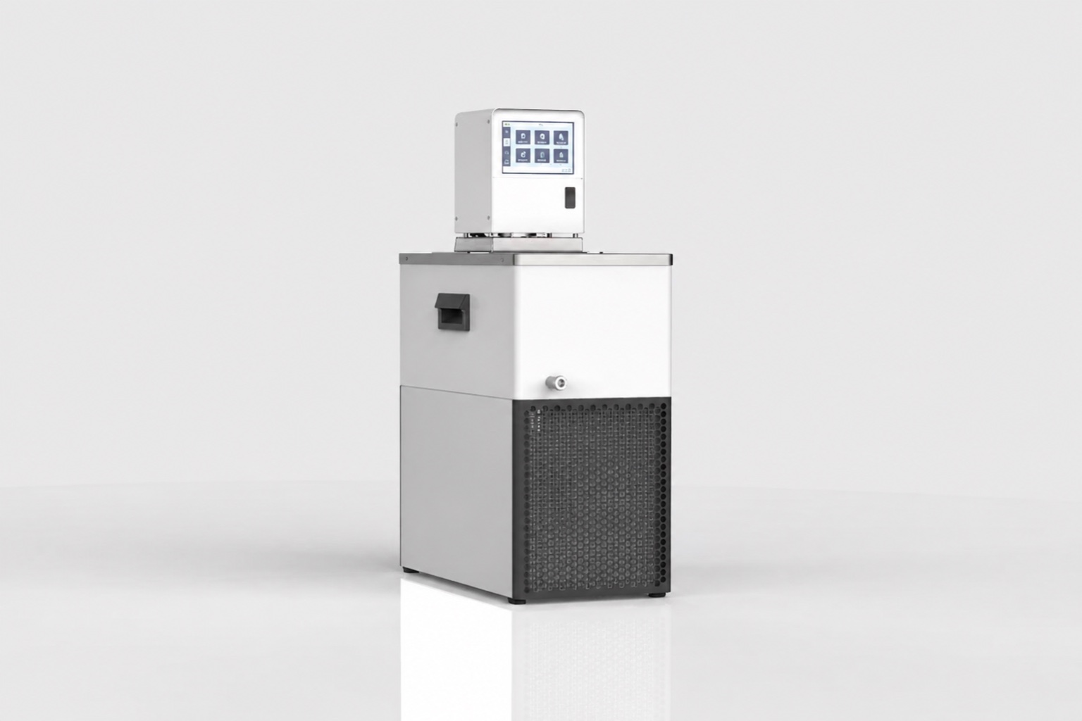 Placement determines what chiller low flow protection can actually see.
| Location | Detects | Misses |
|---|---|---|
| Chiller outlet (supply) | Pump failure, chiller-side blockage | Restrictions downstream in the user’s loop |
| Chiller inlet (return) | Anything that stops flow anywhere in the loop | Little — this is the most complete position |
| Immediately before the application | Restriction in the supply leg | Restriction in the return leg |
For a loop assembled by the user around a benchtop chiller, the return line into the chiller is the position that sees the most failure modes, because everything upstream has to pass through it. Practical points regardless of position:
- Give the switch straight run before and after it. Mounting immediately downstream of an elbow or a coupling produces turbulence that makes the trip point unrepeatable.
- Respect the orientation the switch is designed for. A paddle switch mounted in the wrong attitude may not return reliably.
- Check the fluid compatibility of the wetted parts against the glycol or silicone fluid actually in use, and against the temperature it will see.
- Wire it to stop the compressor, not merely to raise an alarm, if the loop is ever run unattended.
Two Different Thresholds, and Only One of Them Is Protection
Discussions of trip points usually conflate two numbers that have different origins and different consequences. Keeping them separate is what makes chiller low flow protection safe rather than merely present.
| Protection threshold | Performance threshold | |
|---|---|---|
| Answers | Below what flow is the evaporator at risk? | Below what flow does my process run warm? |
| Comes from | The chiller manufacturer, for that model | Your own temperature rise tolerance |
| Consequence of crossing it | Frozen or damaged heat exchanger | Out-of-tolerance process |
| Sets the trip point | Yes | No |
The performance threshold is usually the higher of the two, and it is tempting to use it because it can be calculated from information you already have. That is the error: a trip point derived from process tolerance may sit either side of the evaporator’s safe minimum, and if it sits above it the protection is doing nothing when it matters. Deriving a safety limit from a comfort requirement gets the direction of the argument backwards.
The protection threshold is a property of the heat exchanger, not of the loop, and it has to come from the manufacturer’s minimum flow requirement together with any flow switch specification they state. It is not derivable from measurements taken on your installation.
What to Do When the Figure Is Not Published
Minimum evaporator flow is not stated in the published specifications for the MiniCool range, which makes requesting it a prerequisite rather than an optional refinement. An externally fitted switch on a user-assembled loop is a genuinely useful addition — it sees restrictions an internal sensor may not — but it needs a number to be set against.
The order of operations:
- Request the minimum evaporator flow and any flow switch requirement for the specific model. This is the protection threshold and there is no substitute for it.
- Commission the loop with the correct fluid at the intended operating temperature, not at room temperature, and measure actual flow at that condition.
- Confirm that measured flow sits comfortably above the manufacturer’s minimum. If it does not, the loop is wrong before any protection is fitted, and adding a switch will simply reveal that on the first cold day.
- Set the trip point above the manufacturer’s minimum, with enough margin that normal variation does not cause nuisance trips.
- Separately, note the flow below which your process runs out of tolerance. Where that is higher than the trip point, it is an alarm or monitoring threshold — not a shutdown one.
- Verify by throttling the loop until the switch trips, and confirm it operates before flow reaches the manufacturer’s minimum.
Step 6 is the one usually skipped, and it is the only one that proves the protection works. A switch that trips too late is decoration.
Sequence the Startup, Not Just the Trip
A trip point protects a running system. It does nothing about the moment when a system starts, and starting is when the evaporator is most exposed — the compressor can begin removing heat before circulation has established.
Established practice for chilled and glycol systems is a sequence rather than a simultaneous start:
- Start the pump first and allow circulation to establish through the whole loop.
- Prove flow — the flow switch or sensor must confirm circulation, not merely that the pump is energized.
- Only then permit the compressor to run.
The distinction in step 2 matters. A pump that is powered is not the same as a loop that is flowing, and the two differ in exactly the conditions where the difference is dangerous: an air-locked loop after maintenance, a closed valve, or a cold-soaked viscous fluid on a winter morning. Interlocking the compressor to proven flow rather than to pump power is what closes that gap.
Where a machine’s internal control already implements this sequence, the external switch supplements it by covering the user’s loop. Where it does not, the sequence has to be implemented in the installation, and it is worth confirming which case applies before commissioning rather than after.
Nuisance Trips and What They Mean
Chiller low flow protection that cries wolf gets bypassed, and a bypassed flow switch is worse than none because it creates the belief that protection exists. Common causes of nuisance tripping, and their real meaning:
- Trips at startup only. Flow has not yet established, or the fluid is still cold and viscous from an overnight soak. The correct answer is to run the pump first and prove flow before the compressor is permitted, not to bypass the protection or lower the trip point — a bypass window is precisely when an unprotected compressor can run against a stalled loop.
- Trips intermittently under normal operation. Usually turbulence from poor mounting position, or a trip point set too close to normal flow.
- Trips increasingly often over months. This is not nuisance tripping — it is a real and worsening restriction, most often a loading strainer or degrading fluid. Treat it as a maintenance signal.
- Trips only when a second instrument is connected. The loop is at its flow limit and the manifold split is uneven.
Routine checks that keep flow protection meaningful are part of a broader schedule discussed in our laboratory chiller maintenance schedule.
Where This Sits in the Product Range
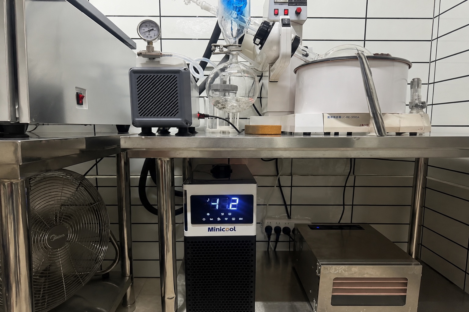 Flow protection is a loop-level concern rather than a model-level one, but the machine determines the operating envelope it has to protect.
| Model | Published capacity | Temperature range | Why flow protection matters |
|---|---|---|---|
| MiniCool 450 / 800 / 850 | 450 W / 800 W / 850 W | 0 °C to −40 °C | Sub-zero fluid; viscosity runaway on restriction |
| DV compact liquid chiller | 100–550 W | −20 °C to +20 °C | Positive-temperature loops; freeze risk near 0 °C |
The sub-zero range is where the self-reinforcing viscosity mechanism applies, which is why protection deserves more attention there than on a chilled-water loop. Full model data is on the MiniCool product page, and positive-temperature loops are served by the DV compact liquid chiller range.
If you would rather have the trip point specified than guessed, send the following and our engineers will advise: coolant fluid and concentration, operating setpoint, hose length and internal diameter, application internal geometry, number of instruments on the loop, acceptable temperature rise across the load, and whether the system runs unattended. Send your loop details to our engineering team.
Frequently Asked Questions
What does a flow switch actually protect on a small chiller?
On a sub-zero loop the primary exposure is the evaporator, not the pump. Reduced flow drives local fluid temperature down until it can freeze or turn to slush against the heat exchanger, and on the refrigerant side incomplete evaporation can return liquid to the compressor. Chiller low flow protection stops the machine before either of those completes. Pump dry-running is a real concern too, but it is the cheaper failure.
Why does a small flow restriction get worse instead of stabilizing?
Because viscosity and temperature are coupled below 0 °C. Less flow means the fluid leaves the evaporator colder, colder fluid is more viscous, and more viscous fluid flows less through the same restriction. The loop moves to a worse operating point on its own rather than settling. Above 0 °C the same coupling exists but is far weaker, which is why sub-zero loops deserve more protection than chilled-water loops.
How do I tell a flow problem from an undersized chiller?
Measure the temperature rise across the application and the gap between chiller supply and process inlet. A flow problem shows the chiller at or below setpoint with a large rise across the load. A capacity problem shows the chiller above setpoint and running continuously. If the chiller says it has reached setpoint but the process is warm, adding capacity will not help.
Where should the flow switch go?
On a user-assembled loop, the return line into the chiller sees the most failure modes because everything upstream must pass through it. Give it straight run before and after, respect its mounting orientation, and confirm the wetted materials suit the glycol or silicone fluid at the temperature it will see.
My flow switch trips every morning at startup. What should I change?
Sequence the start rather than bypassing the protection. Run the pump alone first and let it establish circulation through cold, viscous fluid, and only permit the compressor once flow is proven. That addresses the cause — flow has not yet established — without creating a window in which the compressor can run against a stalled loop. Do not lower the trip point either: that removes protection for the rest of the day, which is when a real restriction would appear. If the pump alone cannot establish flow after a cold soak, the coolant is too viscous for the loop at that temperature and the fluid specification needs revisiting.
Can I put two instruments on one chiller loop?
Only if total flow is sufficient at the operating temperature and the split between them is reasonably even. The characteristic failure is that each instrument holds temperature correctly on its own and neither holds when both run. Check the temperature rise across each branch with both connected, at the actual setpoint rather than at room temperature.