
Cooling Vest Connector Durability Industrial Crews Actually Need — A Field Notes Deep Dive
Here is a pattern that repeats across foundries, glass plants, smelters, and heavy fabrication shops: a cooling vest system arrives on-site, the compressor runs fine for months, and then one Tuesday afternoon the whole rig gets shelved — not because the motor quit, but because a quick-disconnect coupling started weeping coolant onto somebody’s hip. The hose fitting cracked. The O-ring swelled. The barb corroded under a crust ofiteite powder and dried sweat.
Connector durability is the unglamorous gatekeeper of whether a liquid-cooling vest actually survives six months of daily industrial use. This article is not a how-to guide. It is a field-level examination of what kills fittings, how dust and perspiration accelerate that process, and what integration decisions separate a rig that lasts from one that becomes a shelf ornament by Week 22.
If you manage PPE programs, write maintenance schedules, or sign purchase orders for thermal-protection equipment, this is the article you read before the spec sheet.
The Operating Reality: Dust, Sweat, and Wash Cycles
Industrial cooling vest deployments share a set of environmental stressors that office-adjacent applications — data-center techs, broadcast crews — rarely face at the same intensity:
- Airborne particulate. Silica fines, metal grinding dust,ite fiber fragments,ite calcium powder. These particles embed in every crevice that is not sealed flush. Quick-disconnect collars, threaded adapters, and hose-barb junctions are prime targets.
- Salt-loaded perspiration. A worker in a 120 °F environment wearing a cooling vest under FR coveralls can produce more than a liter of sweat per hour. That moisture wicks along hose runs, pools around connector shoulders, and — critically — deposits salt crystals as it dries between shifts.
- Frequent cleaning. Industrial hygiene protocols often require daily or per-shift wipe-downs. In food-adjacent or pharmaceutical-adjacent plants, full wash-down with mild detergent or quaternary ammonium solutions is standard. Each cleaning event is a mechanical stress event for every fitting in the loop.
The combination is corrosive in the literal, chemical sense. Salt accelerates galvanic corrosion between dissimilar metals. Dust acts as an abrasive during insertion and removal of quick-disconnect fittings. Detergent residue attacks certain elastomer seals. And the repetitive connect-disconnect-clean-reconnect cycle accumulates fatigue on latch mechanisms and threads alike.
Anatomy of a Cooling Vest Fluid Circuit — Where Durability Matters Most
A liquid-cooled vest system has a surprisingly short bill of materials for the fluid path. Understanding each junction point matters because each one is a potential failure origin:
- Chiller outlet port. Where cooled fluid exits the refrigeration unit. Typically a barbed or push-to-connect fitting.
- Supply hose run. Flexible tubing, usually 6–10 mm ID, running from the chiller to the vest. Length varies by mounting configuration — belt-mounted chillers keep it short; cart-mounted units may need 1.5 meters or more.
- Vest inlet quick-disconnect. The single most handled fitting in the system. Workers connect and disconnect this every time they don or doff the vest. In a typical shift, that is a minimum of two cycles; in practice, bathroom breaks, lunch, and task rotations push it to four or six.
- Internal vest manifold. The distribution tubing sewn or laminated into the vest itself. Less exposed to external contamination but subject to kinking and abrasion against FR garments.
- Vest outlet quick-disconnect. The return-side fitting. Same handling stress as the inlet, plus it carries warmer fluid that may deposit more mineral content.
- Return hose run. Back to the chiller’s inlet port.
Of these six zones, items 3 and 5 — the quick-disconnect pairs — account for the vast majority of field failures in our experience. The hoses themselves are comparatively robust. The chiller ports are stationary. But the QD fittings live at the intersection of every stressor: dust exposure, sweat contact, mechanical handling, and cleaning chemistry.
Failure Mode #1: Elastomer Seal Degradation
Every quick-disconnect fitting relies on an elastomer O-ring or gasket to seal against coolant leakage when mated. The three most common seal materials in cooling vest fittings are:
- Buna-N (nitrile). Good general-purpose resistance to water-glycol mixtures. Economical. Vulnerable to ozone, UV, and certain cleaning solvents.
- EPDM. Excellent resistance to water, steam, and many cleaning chemicals. Poor resistance to petroleum-based lubricants (rarely an issue in vest systems, but worth noting if the chiller sits on a greasy shop floor).
- Viton (FKM). Premium chemical resistance across a broad spectrum. Higher cost. Stiffens at low temperatures but performs well in the 35–100 °F range typical of vest cooling loops.
In dusty industrial environments, the failure sequence is predictable:
- Fine particulate accumulates on the male and female halves of the QD fitting between connections.
- When the worker clicks the fitting together, particles get trapped between the seal face and the mating surface.
- Over dozens of cycles, these particles score the seal. Micro-channels form.
- Coolant begins to weep — slowly at first, then visibly once the channel erodes further.
Field experience note: In our observation across multiple deployment environments, fittings that are blown clean with compressed air or wiped with a damp cloth before each connection last roughly two to three times longer than fittings that are simply clicked together as-is. This is an operational discipline issue as much as a hardware issue.
Failure Mode #2: Galvanic and Crevice Corrosion at Metal Interfaces
Many mid-tier quick-disconnect fittings use a combination of brass bodies, stainless-steel latch sleeves, and nickel or chrome plating. In a clean, dry environment, this works fine. In an environment where salt-laden sweat pools in the latch collar and dries overnight, it creates a textbook galvanic cell.
Symptoms appear as:
- Green or white powdery deposits around the fitting collar.
- Increasing force required to engage or disengage the latch.
- Eventually, latch seizure — the fitting either will not connect or will not release without pliers.
Crevice corrosion compounds the problem. The narrow gap between the latch sleeve and the fitting body traps moisture, creating an oxygen-depleted zone that accelerates localized attack. This is particularly aggressive in environments with airborne chlorides — coastal facilities, certain chemical plants, and anywhere road salt is tracked indoors during winter months.
Field experience note: All-stainless-steel QD fittings eliminate the galvanic issue but cost two to four times more than brass-bodied alternatives. For deployments where vests are shared across shifts (common in foundry and glass operations), the stainless premium typically pays for itself within the first replacement cycle — roughly the three to four month mark based on typical field observations.
Failure Mode #3: Hose-Barb Fatigue and Pull-Out
The junction between flexible tubing and a rigid barb fitting is a chronic stress riser. Every time a worker moves, bends, or tugs the hose, the tubing flexes at the barb shoulder. Over hundreds of cycles, the tubing material fatigues, softens, and eventually loses its grip on the barb ridges.
Contributing factors in industrial settings:
- Heat cycling. The hose alternates between carrying chilled fluid (which contracts the tubing) and ambient warming during breaks (which relaxes it). This thermal cycling loosens the interference fit.
- Chemical exposure. Cleaning agents — even mild ones — can plasticize certain tubing compounds, reducing their elastic memory.
- Routing strain. If the hose run between chiller and vest is too short, every torso twist creates a pull load at both barb junctions. If too long, excess tubing snags on equipment and creates sudden jerk loads.
Mitigation that works: Double-clamped barb fittings — one clamp at the barb shoulder, one 15 mm behind it — resist pull-out far better than single-clamped or friction-only connections. Spring clamps are faster to service than screw clamps but lose tension over time in high-vibration environments (near presses, hammers, or compactors). For high-vibration zones, worm-drive clamps with a periodic re-torque schedule are preferable.
The Cleaning Question: How Wash Protocols Affect Connector Lifespan
Maintenance teams understandably want to keep cooling vests clean. In dusty environments, a vest that is not cleaned daily becomes a respiratory hazard when donned the next morning — particles shake loose near the breathing zone. In environments with chemical splash risk, contaminated vests must be decontaminated per OSHA or site-specific protocols.
But every cleaning event stresses the connectors:
- Disconnection and reconnection. Each cycle wears the latch, compresses the seal, and opens the fitting to contamination.
- Fluid exposure. Water, detergent solutions, and sanitizers contact seal faces, plated surfaces, and tubing ends.
- Drying method. Compressed air blow-off can drive particles into fitting bores. Hang-drying in dusty environments deposits new contamination. Oven-drying (used in some decon protocols) accelerates elastomer aging.
There is a practical tension here: cleaning extends the vest’s hygiene life but shortens its connector life. The resolution is not to clean less — it is to design the cleaning protocol around the connectors:
- Disconnect fittings before cleaning. Clean the vest and fittings separately.
- Cap or plug open fitting halves during the wash cycle to prevent detergent intrusion into the fluid path.
- Rinse fitting faces with clean water and dry with a lint-free cloth before reconnection.
- Apply a thin film of food-grade silicone lubricant to O-rings monthly (or per manufacturer specification).
- Inspect latch mechanisms weekly. Replace any fitting where the latch no longer clicks positively — a soft latch is a leak waiting to happen.
This protocol adds roughly 90 seconds per vest per cleaning event. For a 10-vest fleet cleaned daily, that is 15 minutes of technician time. Measured against the cost of replacing fittings or entire vest assemblies, it is a high-ROI investment.
Selecting a Chiller That Does Not Punish Its Own Connectors
The chiller unit itself influences connector durability in ways that are not immediately obvious:
- Vibration output. Compressor-driven chillers transmit vibration through the chassis to the outlet and inlet ports. Over time, this vibration fatigues barb connections and loosens threaded fittings. Lower-vibration compressor designs — particularly rotary types — impose less mechanical stress on the fluid connections.
- Thermal stability. A chiller that cycles aggressively between on and off states creates repeated thermal shock at every fitting in the loop. A unit that modulates cooling output more smoothly reduces the expansion-contraction cycling that loosens seals.
- Port orientation and accessibility. If the chiller’s inlet and outlet ports are recessed, awkwardly angled, or require tools to access, field technicians are more likely to apply excessive force during connection — bending barbs, cross-threading adapters, or stressing hose runs.
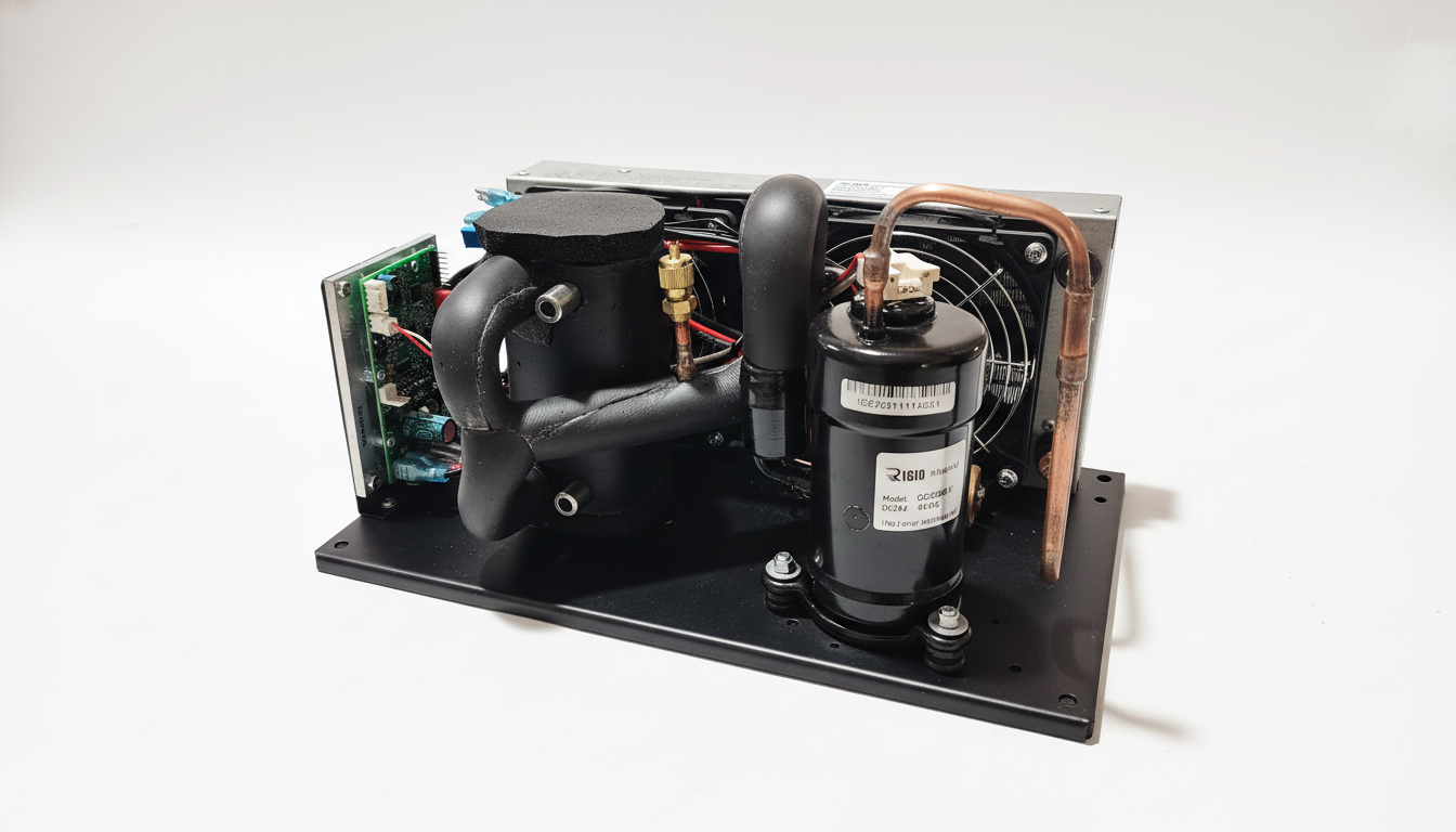
The RIGID Micro Cooler addresses several of these concerns through its design architecture. Its rotary micro-compressor produces lower vibration signatures than reciprocating alternatives, which reduces the cyclic mechanical load transmitted to port fittings. The sealed Freon refrigerant circuit means the cooling loop fluid never contacts the compressor internals — eliminating a contamination vector that can degrade seals in open-system designs. At under 7 kg (15 lbs), the unit’s portability also means shorter hose runs when belt-mounted, which reduces routing strain on barb connections. The system cools to below 35 °F, drawing a maximum of 18–22 amps depending on installation and environmental conditions, and requires no ice — removing the condensation and melt-water issues that plague ice-based systems’ fittings.
Integration Planning: Matching Connectors to Your Deployment Profile
Not every industrial cooling vest deployment faces the same connector stress profile. Before standardizing on a fitting type, map your specific conditions:
| Factor | Low Stress | Moderate Stress | High Stress |
|---|---|---|---|
| Airborne particulate | Office / control room | Light manufacturing | Foundry, grinding, demolition |
| Sweat exposure | Climate-controlled facility | Warm warehouse | Furnace-side, outdoor summer |
| Connect/disconnect cycles per shift | 1–2 | 3–4 | 5+ |
| Cleaning frequency | Weekly | Daily wipe | Full wash every shift |
| Cleaning chemistry | Water only | Mild detergent | QAC / bleach solution |
| Vibration environment | Static workstation | Mobile, smooth floors | Near presses / hammers |
For low-stress profiles, standard brass QD fittings with Buna-N seals are adequate and cost-effective. Expect six months or more of service life with basic maintenance.
For moderate-stress profiles, upgrade to EPDM seals and consider stainless-steel latch sleeves. Implement the capped-cleaning protocol described above. Plan for fitting inspection every 60 days.
For high-stress profiles — and this is where most foundry, glass, and heavy-fabrication deployments land — specify all-stainless QD fittings with Viton seals, double-clamped barb junctions, and a formal connector maintenance log. Budget for a full fitting replacement at the four-month mark as a preventive measure rather than waiting for leaks.
What This System Is — and Is Not — Built For
Clarity on application boundaries prevents expensive mismatches:
Well-suited applications:
- Individual worker cooling in stationary or semi-mobile industrial roles — furnace tending, welding stations, glass forming lines, kiln loading.
- Environments where ice logistics are impractical — remote sites, confined spaces, elevated platforms where hauling coolers is a safety risk.
- Shift-based operations where vest systems are shared across workers (with appropriate hygiene protocols).
- Applications requiring consistent sub-ambient cooling over multi-hour duty cycles without performance degradation.
Less suitable applications:
- Fully submerged or continuous-spray wet environments where the chiller unit itself would require IP67+ enclosure protection beyond its standard rating.
- Explosive-atmosphere (ATEX/IECEx) zones unless the specific unit has been certified for that classification — standard cooling vest systems, including the Micro Cooler, are not inherently explosion-proof.
- Applications requiring more than approximately 2 meters of hose run between chiller and vest, as the thermal loss and connector strain at that distance begin to degrade both cooling performance and fitting longevity.
- Environments exceeding 150 °F ambient sustained, where the chiller’s condenser efficiency drops and the system works harder — accelerating wear on all components, including connectors.
Spare Parts Strategy and Lifecycle Budgeting
Connector durability is ultimately a cost-management question. The fittings are consumable components — they will wear out. The question is whether you plan for that or react to it.
A pragmatic spare-parts inventory for a 10-vest industrial fleet includes:
- 20 complete QD fitting pairs (inlet + outlet, male + female halves). This covers one full replacement cycle for every vest plus a 100% buffer.
- 40 replacement O-rings in the correct material for your cleaning chemistry. O-rings are cheap; downtime is not.
- 10 meters of replacement tubing in the correct ID and material. Pre-cut to your standard hose-run length.
- 20 hose clamps of the appropriate type for your vibration environment.
- Silicone lubricant, lint-free wipes, and a set of dust caps for every fitting pair.
Field experience note: Based on observations from demanding deployment environments, teams that pre-stage these parts and perform scheduled fitting swaps at defined intervals (typically around the four-month mark for high-stress environments) report significantly fewer unplanned cooling-system outages than teams that run fittings to failure. The unplanned failure mode is almost always a leak that contaminates the worker’s garments, creates a slip hazard, or — at minimum — takes a vest out of rotation for the remainder of the shift while someone hunts for a replacement fitting.
Documentation That Pays for Itself
For multi-vest deployments, a simple tracking log prevents the slow drift toward deferred maintenance:
- Vest ID. Assign a unique tag to each vest and chiller pair.
- Fitting install date. When the current QD fittings were installed or last replaced.
- Cumulative connect/disconnect cycles. Estimate based on shifts worked. Four cycles per shift is a reasonable default for most industrial roles.
- Cleaning events. Tally of full wash-downs (as opposed to surface wipes).
- Inspection notes. Latch condition, seal condition, visible corrosion, drip test results.
- Replacement trigger. Define a replacement threshold — either a cycle count, a time interval, or a condition-based criterion (first sign of weeping, latch force exceeds X, etc.).
This log does not need to be software. A laminated card zip-tied to each chiller unit works. The point is that someone is looking at the fittings on a schedule rather than discovering a failure when a worker complains about a wet shirt.
Closing Perspective: Connectors Are the Immune System of the Cooling Loop
In industrial cooling vest integration, the compressor gets all the attention. It is the engine, the expensive part, the thing with a spec sheet. But connectors are the immune system — when they are healthy, nobody thinks about them. When they fail, the entire system is compromised regardless of how well the compressor performs.
Investing in connector durability — through material selection, cleaning protocols, spare-parts planning, and honest application-boundary assessment — is what separates a cooling program that delivers measurable heat-stress reduction over a full season from one that generates a drawer full of broken fittings and a procurement team that swears off liquid cooling entirely.
The fittings are small. The decisions around them are not.
For integration support, system specification guidance, or help mapping connector requirements to your specific industrial environment, the RIGID technical team can consult on deployment planning. Reach out before you finalize your connector spec — it is easier to get the fittings right on the first order than to retrofit a fleet mid-season.