
Cryocooler Dewar Integration Trades Thermal Resistance Against Vibration
Mounting a cryocooler cold finger into a dewar looks like a mechanical problem and is really a pair of competing thermal and dynamic requirements. The cold finger has to conduct heat out of the load efficiently, which argues for a short, stiff, high-conductivity connection. It also has to avoid transmitting the machine’s mechanical disturbance into the instrument, which argues for exactly the opposite.
Established practice recognizes the tension explicitly. NASA work on cold finger interfaces has pursued flexible thermal straps with multiple degrees of freedom specifically to mitigate vibration propagation while minimizing thermal resistance and weight — three objectives that pull against each other. Cryocooler dewar integration is the design of a compromise, and knowing which side to err on requires knowing what the instrument actually cannot tolerate.
This guide covers the interface options, the heat paths into the dewar that determine how much cooling reaches the load, and the practical decisions that get made once rather than iterated.
Where the Heat Actually Comes From
A dewar’s self-heat load reaches the cold end through three paths, and their relative weights are not equal.
| Path | Behavior in an evacuated dewar | Design lever |
|---|---|---|
| Conduction | Through supports, wiring and any mechanical path to the warm shell | Long, thin, low-conductivity supports; thermal intercepts |
| Radiation | Between warm shell and cold surfaces, rising steeply with temperature difference | Multilayer insulation, low-emissivity surfaces, radiation shields |
| Convection | Negligible once the envelope is evacuated | Maintain vacuum integrity |
The third row is the one that makes dewars work at all — convection losses in an evacuated envelope are negligible, which is why vacuum is not an optimization but a precondition. It also means that a small vacuum leak does not degrade performance gradually; it reintroduces an entire heat transfer mechanism that the design had eliminated.
The practical consequence for cryocooler dewar integration is that vacuum integrity at the cold finger penetration is not a sealing detail. It is the assumption everything else rests on.
The Interface Options
Direct rigid mounting
The simplest cryocooler dewar integration bolts or clamps the cold finger directly to the load. Lowest thermal resistance, simplest assembly, and full transmission of the machine’s mechanical disturbance into the instrument. Suitable where the instrument is genuinely vibration-tolerant, and unsuitable where it is not — which is more applications than people expect, since many cryogenic instruments exist precisely because they are measuring something small.
Flexible thermal strap
A braided or foil strap between cold finger and load, decoupling them mechanically while maintaining a conduction path. This is the approach NASA work has developed toward six degrees of freedom, and the design problem is that every unit of flexibility costs thermal conductance. The strap has to be sized so its thermal resistance is small relative to the cooling budget while its stiffness is small relative to what the instrument tolerates.
Strap plus rigid backup
A less common arrangement fits a flexible strap for normal running alongside a clampable rigid path used only during cooldown. The rigid path shortens the descent, when vibration is irrelevant because no measurement is being taken, and is released once the instrument is at temperature. It adds a mechanism and a procedure, and it is worth the complexity only where cooldown time is a genuine constraint rather than an inconvenience.
Integrated assembly
Rather than integrating a cooler into a dewar in the field, the two are supplied as one unit — the Integrated Dewar Cooler Assembly approach. Standardized geometry, such as the SADA II specification requiring particular dimensions for field integration, exists so that expanders can be dropped into dewar assemblies by the sensor manufacturer. This removes the interface design problem by settling it in advance, at the cost of flexibility.
Budgeting the Thermal Resistance
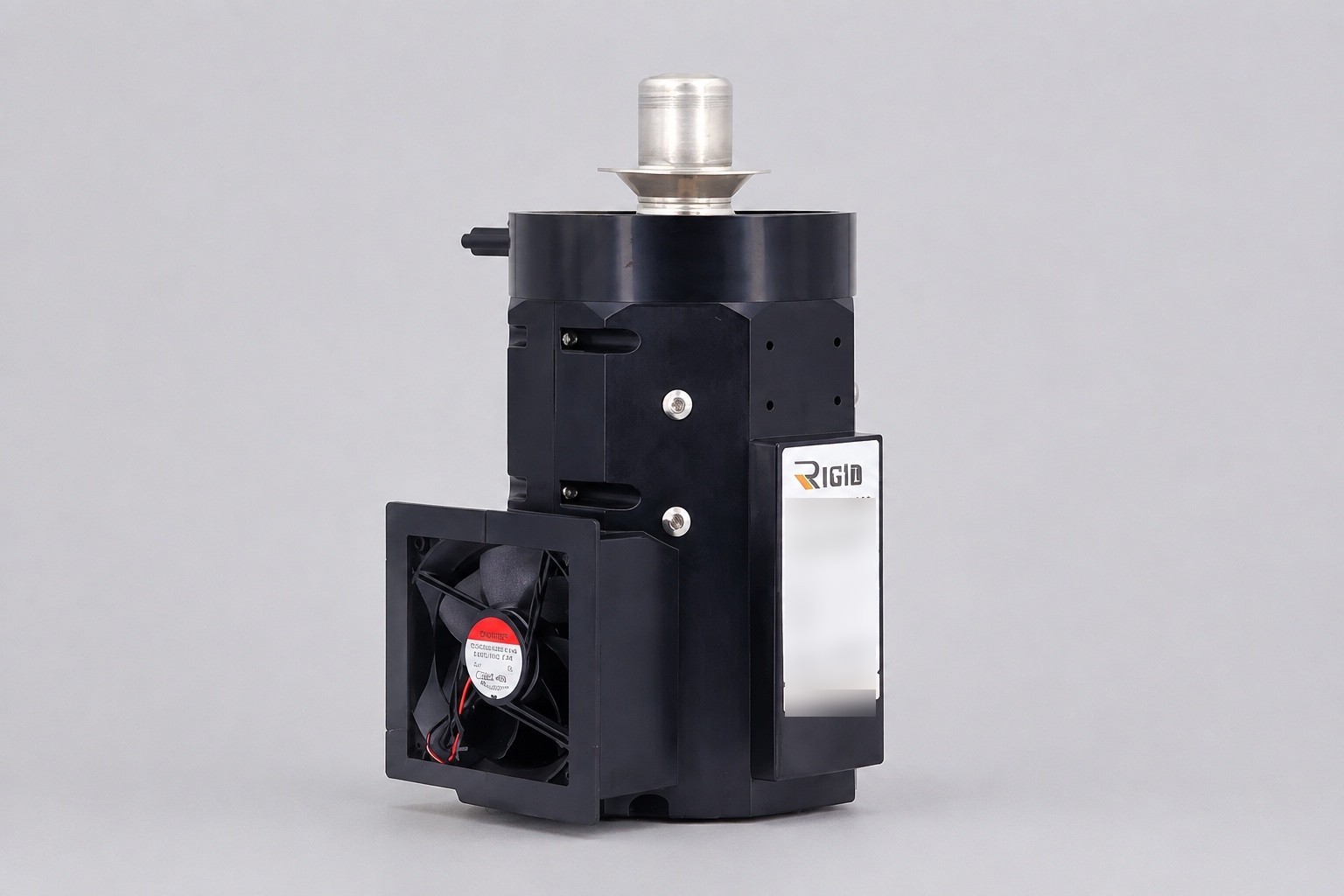 The interface consumes part of the temperature difference the cooler produces, and that consumption is often larger than expected.
The relationship is simple: temperature drop across the interface equals heat flow multiplied by thermal resistance. If the load dissipates 5 W and the strap presents 1 K/W, the load sits 5 K above the cold finger. On a machine whose specification is quoted at the cold finger, that difference is subtracted directly from what the instrument receives.
Three consequences follow for cryocooler dewar integration:
- The cooler must be selected for the load temperature, not the cold finger temperature. Those differ by the interface drop, and it is a real number, not a rounding error.
- Contact resistance at every bolted or clamped joint adds to the total, and it is sensitive to surface finish, flatness and clamping force. A joint assembled without attention can dominate the budget.
- The drop varies with load, so an instrument that dissipates more during operation than at idle sits at a different temperature in each state.
Radiation deserves a note alongside conduction here, because the two interact. Adding shielding reduces radiative load but adds mass and mechanical paths, and every support for a shield is a conduction path of its own. The established answer is long, thin, low-conductivity supports with thermal intercepts, but each one is a compromise between structural adequacy and heat leak — which is the same trade as the cold finger interface, appearing again at a smaller scale.
Measure it rather than assume it: with the system cold and running, the difference between cold finger and load temperature is the interface drop, and it is the number to compare against the budget.
Vibration: Frequency Matters More Than Amplitude
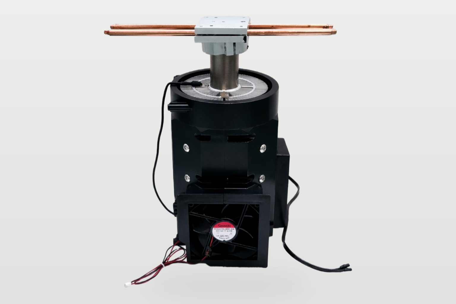 The vibration side of cryocooler dewar integration is rarely a question of how much the machine vibrates. It is whether the disturbance lands in a band the instrument cares about.
A free-piston Stirling machine runs at a comparatively high frequency, which is easier to isolate mechanically than a low-frequency disturbance and generally sits above the band that affects slow measurements. Where it still matters, the levers are:
- A flexible strap, sized as described above.
- Mounting the machine on isolators so the disturbance is attenuated before it reaches the dewar structure.
- Orientation, since the disturbance is not isotropic and some axes matter more to the instrument than others.
- Where possible, synchronizing measurement to the machine’s cycle rather than isolating from it.
Machine orientation also has thermal implications on some designs, so the vibration-driven choice and the thermal one need to be made together rather than sequentially. Orientation and vibration considerations for this range are discussed in our cryocooler integration guide for confined installations.
Cooldown Time and Thermal Mass in the Dewar
Steady-state performance gets most of the attention, but the mass inside the dewar determines how long it takes to get there — and on an instrument that is switched on and off, that time is part of the working day.
Everything the cold finger is connected to has to be cooled: the load itself, the strap or mounting hardware, the shields, and any wiring in thermal contact. The energy required is the sum of each mass times its specific heat times the temperature span, and specific heat falls substantially at cryogenic temperatures — which means the arithmetic done with room-temperature properties overstates the requirement at the cold end and understates it at the start.
Two practical consequences. Cooldown is dominated by the first part of the descent, where properties are closest to room-temperature values and the temperature difference driving heat flow is largest. And anything added to the cold mass for mechanical or electrical reasons — a heavier mount, an extra shield, additional instrumentation wiring — lengthens every cooldown for the life of the instrument.
Where cooldown time is a requirement rather than an outcome, it belongs in the specification alongside the steady-state temperature, because the two can point at different machines.
Practical Assembly Decisions
- Establish the load temperature required and the heat it dissipates, then add the expected interface drop before selecting a machine.
- Decide the vibration requirement in terms the instrument’s designer would recognize — amplitude in a frequency band, not a general preference for less.
- Choose the interface type from those two numbers rather than from assembly convenience.
- Design the vacuum penetration at the cold finger as a primary sealing feature, not a secondary one.
- Specify surface finish, flatness and clamping force at every conduction joint, and use a thermal interface material rated for the temperature.
- Include radiation shielding and low-emissivity treatment, since radiation grows steeply with the temperature difference the design creates.
- Verify by measuring cold finger and load temperatures separately once cold, and comparing the difference against the budget.
- Record the assembled interface resistance and the cooldown time as commissioning data, so a later change to the assembly can be judged against a baseline rather than against memory.
- Confirm heat rejection at the warm end at the same time, since a cooler that cannot reject properly will not deliver its cold-end specification regardless of interface quality.
Step 7 is what separates a validated assembly from an assumed one, and it costs one additional sensor.
Model data for the FPSC range — RS40 at 40 W to −100 °C, RS100 at 100 W to −150 °C, RS100 Plus 77K at over 5 W at −196 °C — is on the FPSC Stirling cooler product page. Where the warm end is rejected to liquid rather than air, the DV compact liquid chiller range covers smaller rejection duties. Cycle-level selection is covered in our Stirling cryocooler selection guide.
If you want an interface design reviewed, send the following and our engineers will advise: required load temperature and dissipated power at that temperature, acceptable vibration amplitude and frequency band at the instrument, dewar geometry and available penetration, whether the assembly must be field-serviceable, mounting orientation constraints, and the available warm-end rejection path. Send your assembly details to our engineering team.
Frequently Asked Questions
Should the cold finger be rigidly mounted or use a flexible strap?
It depends on whether the instrument tolerates the machine’s mechanical disturbance. Rigid mounting gives the lowest thermal resistance and transmits everything; a flexible strap decouples mechanically at the cost of conductance. Established work on cryocooler dewar integration has pursued straps with multiple degrees of freedom precisely because minimizing vibration, thermal resistance and weight simultaneously is not possible — one of them gives.
How much temperature do I lose across the interface?
Heat flow multiplied by thermal resistance. A 5 W load across a 1 K/W interface sits 5 K above the cold finger, and that difference comes directly out of the specification quoted at the finger. Select the machine for the load temperature rather than the finger temperature, and measure the actual drop once cold rather than trusting the calculation.
Why does vacuum quality matter so much?
Because convection losses in an evacuated dewar envelope are negligible, which means the design has eliminated an entire heat transfer mechanism. A vacuum leak does not degrade performance gradually — it reintroduces convection, and the cold end sees a load the design never accounted for. Vacuum integrity at the cold finger penetration is therefore a primary sealing requirement, not a detail.
What is an Integrated Dewar Cooler Assembly?
A cooler and dewar supplied as a single unit rather than integrated in the field. Standardized geometry such as the SADA II specification exists so expanders can be dropped into dewar assemblies by sensor manufacturers, which settles the interface design in advance. The trade is reduced flexibility against a removed engineering problem, and it suits volume applications better than one-off instruments.
Does contact resistance at bolted joints matter?
Substantially, and it is the term most often underestimated. Contact resistance depends on surface finish, flatness and clamping force, and a joint assembled without attention to those can dominate the interface budget. Specify them, use a thermal interface material rated for the temperature, and verify the assembled drop by measurement rather than by calculation.
Can I reduce vibration by mounting the machine differently?
Often yes. Isolators between the machine and the dewar structure attenuate the disturbance before it reaches the instrument, and orientation matters because the disturbance is not equal in all axes. Some designs also have orientation-dependent thermal behavior, so the mechanical and thermal decisions need to be made together rather than one after the other.