

Get A Sample Online
Abstract
This document describes the operating principles, thermal performance, and application advantages of the FPSC Stirling Cryocooler integrated with Heat Pipe (Thermal Pipe) technology. Special emphasis is placed on unidirectional (diode) heat pipe architectures, enabling controlled heat flow, thermal isolation, and enhanced system reliability in demanding environments such as cryogenics, aerospace, scientific instrumentation, and remote thermal management systems.
1. Introduction
Efficient thermal transport is a critical challenge in compact, high-performance cooling systems—particularly when heat must be moved away from sources located in confined, sealed, or thermally inaccessible spaces.
Heat pipes provide a passive, highly reliable solution capable of transferring heat over long distances with negligible temperature loss, making them ideal companions for Stirling cryocoolers where precise thermal control and low parasitic losses are essential.

2. Heat Pipe Construction and Operating Principle
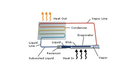
A heat pipe consists of a hermetically sealed tube whose internal surface is lined with a porous wick structure. The wick is saturated with a working fluid and the pipe is evacuated and sealed under vacuum, lowering the fluid’s boiling point.
Operating Cycle
-
Evaporation
Heat applied at the evaporator section causes the working fluid to evaporate, absorbing latent heat. -
Vapor Transport
Vapor flows rapidly through the pipe to the colder condenser section with minimal thermal resistance. -
Condensation
Heat is rejected at the condenser via air or liquid cooling, condensing the vapor back into liquid. -
Capillary Return
Capillary forces in the wick return the liquid to the evaporator, completing a closed-loop cycle.
Key Thermal Characteristics
-
Temperature drop along vapor path: ~1 °C, independent of pipe length
-
No moving parts → silent, vibration-free operation
-
Extremely high effective thermal conductivity
-
Orientation-independent (wick-assisted)
3. Integration with FPSC Stirling Cryocooler
When combined with an FPSC Stirling Cryocooler, the heat pipe enables:
-
Physical separation between cold source and heat rejection point
-
Reduced mechanical and thermal constraints on system layout
-
Improved cryocooler efficiency through stable thermal interfaces
-
Enhanced system reliability and serviceability
This architecture is especially advantageous in applications where direct heat sinking is impractical or impossible.


4. Diode Heat Pipe Technology
Standard heat pipes are bidirectional. In systems where reverse heat flow is undesirable, diode heat pipes are employed to enforce thermal rectification.
Types of Diode Heat Pipes
-
Liquid Trap Diode Heat Pipe
-
Vapor Trap Diode Heat Pipe
-
(Thermosyphon systems also inherently behave as thermal diodes)
5. Liquid Trap Diode Heat Pipe
Design Concept
A liquid trap diode includes a wicked reservoir at the evaporator end that is not hydraulically connected to the main wick.
Normal Operation
-
Operates as a standard heat pipe
-
Vapor flows from evaporator to condenser
-
Condensate returns via capillary action
-
Reservoir dries out and remains inactive
Reverse Temperature Condition
When the condenser becomes hotter than the evaporator:
-
Vapor flows in reverse and condenses in the reservoir
-
Liquid accumulates and becomes trapped
-
Main pipe contains primarily vapor
-
Heat transfer is limited to conduction through the pipe wall
-
Thermal resistance increases by orders of magnitude
Once forward temperature gradient is restored, normal operation resumes automatically.
6. Vapor Trap Diode Heat Pipe
Design Concept
The vapor trap diode incorporates a non-condensable gas (NCG) reservoir located at the condenser end. Unlike the liquid trap diode, the wick structure is continuous.
Normal Operation
-
Vapor flow sweeps NCG into the reservoir
-
NCG remains isolated and inactive
-
Full heat pipe performance is maintained
Reverse Temperature Condition
-
Vapor carries NCG toward the evaporator
-
NCG blocks vapor access to the evaporator
-
Effective thermal conductivity drops sharply
-
Heat transfer occurs only via wall conduction
This design is particularly suited for high-temperature and aerospace environments.
7. High-Temperature Alkali Metal Diode Heat Pipe Case Study
An alkali-metal vapor trap diode heat pipe was developed for a Venus Lander mission.
Performance Summary
-
Normal operation temperature: ~525 °C
-
Reverse heating causes NCG migration
-
Evaporator temperature reduced to ~200 °C
-
System recovers automatically when forward heating resumes
This demonstrates the suitability of diode heat pipes for extreme thermal cycling and harsh environments.
8. Application Diagrams & Captions
Diagram 1 – Heat Pipe Working Principle


Caption:
Evaporation at the heat source generates vapor flow toward the condenser, where heat is rejected and liquid returns via capillary action through the wick.
Diagram 2 – FPSC Stirling Cryocooler with Remote Heat Rejection

Caption:
Heat pipe enables physical separation between the Stirling cryocooler cold head and the remote heat sink, improving layout flexibility and thermal efficiency.
Diagram 3 – Liquid Trap Diode Heat Pipe Operation


Caption:
During reverse temperature gradients, liquid becomes trapped in the reservoir, preventing vapor circulation and suppressing reverse heat flow.
Diagram 4 – Vapor Trap Diode Heat Pipe with NCG


Caption:
Non-condensable gas migrates to block the evaporator during reverse heating, increasing thermal resistance and enforcing unidirectional heat flow.
9. Typical Applications
-
Cryogenic detectors and sensors
-
Infrared imaging systems
-
Aerospace and space exploration instruments
-
Scientific and medical equipment
-
Electronics cooling with restricted airflow
-
Remote or sealed thermal management systems
10. Conclusion
The integration of heat pipe and diode heat pipe technology with FPSC Stirling Cryocoolers enables high-efficiency, passive, and reliable thermal management across a wide range of operating conditions. These systems provide unmatched flexibility, thermal control, and protection against undesirable heat flow, making them ideal for advanced engineering applications.