
Cryocooler Integration Constraints Tight Space: Why the Cold-End Interface Is the First Decision, Not the Last
In compact infrared sensor assemblies—whether mounted inside a gimbal, embedded in a handheld instrument, or packaged into an unmanned aerial vehicle payload—the cryocooler is rarely the largest component. But it is almost always the most demanding in terms of integration geometry. The cold finger must make intimate thermal contact with the detector. The warm end must reject heat to the environment. And the body of the cooler must be mechanically isolated from the detector’s optical path. In a tight enclosure, these three requirements compete for the same cubic centimeters of space.
The cryocooler integration constraints tight space challenge is fundamentally a sequencing problem. Engineers who treat the cold-end interface as a detail to resolve after the optical and electronic layouts are finalized consistently encounter problems that are expensive to fix: thermal contact that cannot be optimized, vibration paths that couple into the detector, and heat rejection that is blocked by adjacent components. This guide addresses the integration sequence head-on, starting with the cold-end interface and working outward.
The Cold-End Interface: Thermal Contact in Millimeters
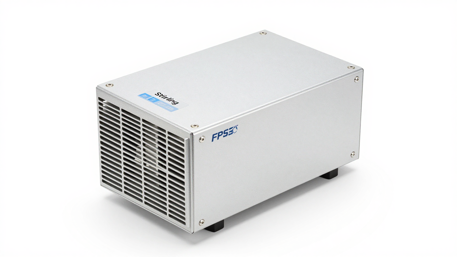
The cold finger of an FPSC Stirling cooler is the thermal bridge between the refrigeration cycle and the detector. Its diameter, length, and termination geometry define the integration envelope for everything downstream. For RIGID FPSC units, the cold finger is a precision-machined copper rod with a typical diameter of 6–12mm and a usable length of 20–40mm, depending on the model.
In a tight-space integration, the cold finger length is the first constraint to resolve. A longer cold finger provides more flexibility in positioning the cooler body relative to the detector, but it introduces additional thermal resistance and increases the thermal time constant of the cold chain. A shorter cold finger minimizes thermal losses but forces the cooler body closer to the detector, which can create vibration coupling and heat rejection conflicts.
Interface termination options:
- Direct contact (butt joint). The cold finger tip presses directly against the detector mounting surface. This provides the lowest thermal resistance but requires precise alignment—typically within ±0.1mm—and a clamping mechanism that maintains contact force through thermal cycling. Best suited for fixed installations where the cooler and detector are permanently assembled.
- Thermal strap (flexible link). A braided copper or aluminum strap connects the cold finger to the detector mount. This decouples the cooler mechanically from the detector, reducing vibration transmission. The trade-off is increased thermal resistance: a typical 50mm copper braid adds 0.3–0.8 K/W depending on cross-section and braid density. In tight spaces, the strap routing itself becomes a packaging challenge.
- Heat pipe (passive transport). A miniature heat pipe transfers cooling power from the cold finger to a remote detector mount. This allows the cooler to be positioned away from the detector—useful when the optical path geometry prevents co-location. Heat pipes add minimal thermal resistance when operating within their design limits, but they have orientation sensitivity and a maximum heat transport capacity that must be matched to the cooling load.
The choice between these three options should be made before the mechanical layout is finalized. Each option defines a different integration envelope, and changing the interface type after the enclosure is designed typically requires a full mechanical redesign.
Warm-End Heat Rejection: The Constraint Nobody Plans For
Every watt of cooling at the cold end must be rejected at the warm end, plus the electrical input power of the cooler itself. For an FPSC unit operating at 60W of cooling capacity with approximately 100W of electrical input, the warm end must dissipate roughly 160W into the surrounding environment. In an open bench setup, this is trivial. In a sealed enclosure with limited airflow, it becomes the dominant integration constraint.
 Heat rejection strategies for tight enclosures:
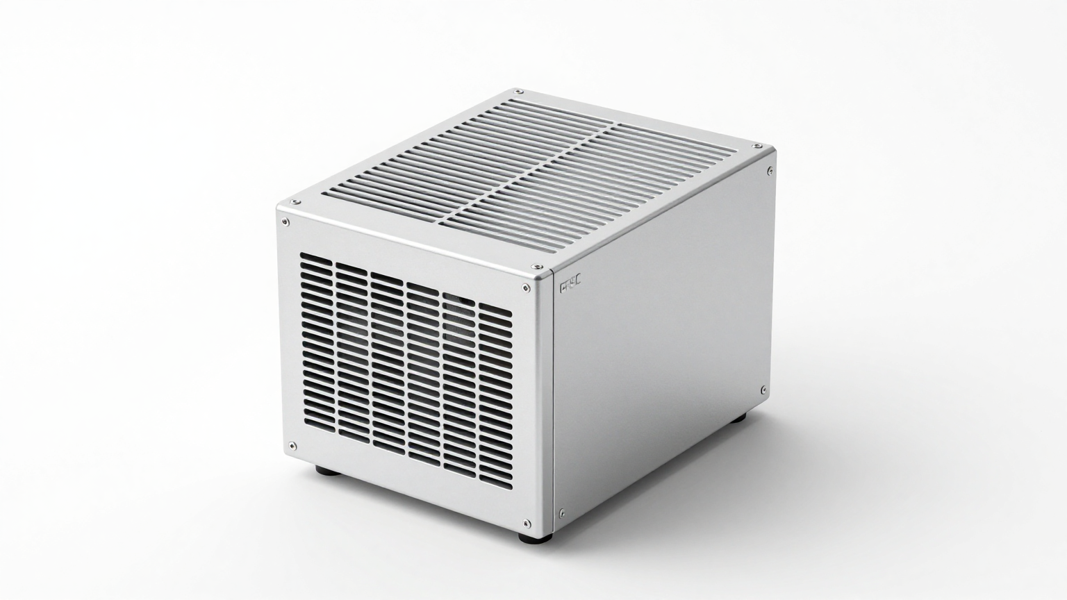
- Forced air with ducting. A small fan (40–60mm) directed at the warm-end heat sink, with inlet and exhaust ducts routed to the enclosure exterior. This is the most common approach and works well when the enclosure design allows two penetrations for airflow. The duct cross-section must be sized to avoid excessive pressure drop—a common mistake in compact designs where the ducts are narrowed to fit the available space.
- Conduction to chassis. The cooler’s warm end is bolted directly to the enclosure wall, which acts as a heat sink. This eliminates the need for internal airflow but requires the enclosure material to have sufficient thermal conductivity (aluminum is typical) and enough external surface area for natural or forced convection. The thermal resistance of the bolted joint is critical—use thermal interface material and maintain bolt torque to specification.
- Liquid cooling loop. A small-diameter tubing loop circulates coolant past the warm-end heat exchanger and rejects heat at a remote radiator. This is the most effective approach for sealed enclosures but adds system complexity, weight, and potential leak points. Reserve this for applications where air cooling is physically impossible.
The warm-end heat rejection path should be designed with at least 20% margin above the calculated heat load. In tight enclosures, the internal air temperature rises quickly if heat rejection is undersized, which reduces the cooler’s net cooling capacity and extends the cool-down and stabilization times.
Vibration Isolation: Keeping the Cooler Out of the Optical Path
FPSC Stirling coolers generate mechanical vibration at the drive frequency (typically 50–60 Hz) and its harmonics. Modern units like the RIGID FPSC series incorporate internal counter-balancing that reduces exported vibration to low levels, but “low” is relative. For a cooled infrared detector operating at the diffraction limit, even microns of displacement at the focal plane can degrade image quality.
In tight-space integrations, the vibration challenge is amplified because the cooler is physically close to the detector. The mechanical path between the two is short, which means there is less opportunity for vibration attenuation through structural compliance.
Isolation approaches:
- Elastomeric mounts. Silicone or fluorocarbon rubber grommets between the cooler body and the mounting structure. These provide broadband vibration isolation but introduce a compliance that allows the cooler to shift position under shock loads. The mount stiffness must be tuned to provide isolation at the drive frequency without allowing excessive displacement under the expected shock and vibration environment.
- Wire rope isolators. Stainless steel cable loops that provide vibration isolation with higher load capacity than elastomers. These are preferred in military and aerospace applications where temperature extremes would degrade rubber compounds. They are more compact than spring-damper systems and can be configured for multi-axis isolation.
- Structural decoupling through thermal strap. If a flexible thermal strap is used for the cold-end interface, it inherently provides some vibration decoupling. The strap acts as a mechanical low-pass filter, attenuating high-frequency vibration while transmitting the static thermal load. This dual function makes thermal straps attractive in tight integrations where dedicated vibration isolators would consume too much space.
Integration Sequence: The Order That Prevents Rework
Based on field experience supporting compact IR system integrations with RIGID FPSC Stirling Coolers, the following sequence minimizes the risk of costly redesigns:
- Define the detector cold-end requirement. Temperature, stability, heat load, and the physical location of the thermal interface on the detector package. This is the fixed point around which everything else is arranged.
- Select the cold-end interface type. Direct contact, thermal strap, or heat pipe. This decision sets the allowable distance between the cooler and the detector, and therefore the cooler’s position within the enclosure.
- Position the cooler body. Orient the cooler so that the warm end faces the most accessible heat rejection path (enclosure wall, airflow duct, or liquid loop connection). Verify that the cold finger or thermal strap can reach the detector interface without interference from other components.
- Design the warm-end heat rejection. Size the heat sink, fan, duct, or liquid loop based on the total heat rejection requirement (cooling load + electrical input). Verify that the thermal path from the warm end to the environment has sufficient conductance.
- Add vibration isolation. Select and position isolators based on the cooler’s exported vibration spectrum and the detector’s sensitivity to mechanical disturbance. Verify that the isolation system does not conflict with the thermal strap or cold-finger alignment.
- Verify the electrical routing. Route power and control cables to the cooler, ensuring they do not cross the detector’s signal path (to avoid electromagnetic interference) and do not obstruct the heat rejection airflow.
Steps 1 and 2 are the foundation. If they are correct, steps 3–6 follow logically. If they are deferred, every subsequent decision becomes a compromise.
Cable and Connector Routing in Confined Volumes
In tight enclosures, the cryocooler’s power and control cables compete for space with the detector’s signal cables, the optical fiber routing, and the structural mounting hardware. This is not merely a packaging inconvenience—it is a potential source of electromagnetic interference (EMI) and thermal obstruction that can degrade system performance.
The cooler’s drive electronics generate high-frequency switching noise. If the power cables run parallel to the detector’s low-noise signal lines, this noise can couple capacitively into the readout circuit, appearing as periodic artifacts in the IR image. The standard mitigation is physical separation: maintain a minimum of 15mm between power and signal cables, and cross them at right angles where they must intersect. In enclosures where 15mm of separation is not achievable, use shielded twisted-pair cabling for the detector signal path, with the shield grounded at one end only to prevent ground loop formation.
Connector selection also matters in confined volumes. Right-angle connectors reduce the vertical clearance required above the cooler’s electrical interface, freeing space for heat rejection or structural elements. However, right-angle connectors with integral strain relief can extend the horizontal footprint. Map the connector envelope—including the cable bend radius—into the 3D model before committing to a connector type. A connector that fits on paper but cannot be mated with human fingers in the actual enclosure is a production bottleneck waiting to happen.
Common Mistakes in Tight-Space Cryocooler Integration
The following errors appear repeatedly in compact IR system designs. Each one is avoidable with proper sequencing.
- Undersized heat rejection. The enclosure is designed for the steady-state heat load, but the cool-down transient generates significantly more heat. During the first 5–10 minutes of operation, the cooler runs at maximum power, and the internal air temperature spikes. If the heat rejection system cannot handle this transient, the enclosure overheats and the cooler’s performance degrades.
- Cold finger misalignment under thermal cycling. The cooler and detector are aligned at room temperature, but differential thermal expansion shifts the cold finger contact point as the system cools. In a direct-contact interface, this can reduce the contact area and increase thermal resistance. Use materials with matched coefficients of thermal expansion, or design the interface with a compliant element that accommodates movement.
- Blocked airflow paths. Cable bundles, circuit boards, or structural brackets are routed through the heat rejection airflow path after the thermal design is complete. Even a partial obstruction can reduce airflow by 30–50%, which in a tight enclosure is the difference between stable operation and thermal runaway.
- Vibration isolation that defeats thermal contact. Soft isolators that provide excellent vibration attenuation also allow the cooler to move relative to the detector. If the cold-end interface is a direct butt joint, this movement degrades thermal contact. The isolation and thermal interface must be designed as a system, not independently.
Frequently Asked Questions
- Q: What is the minimum enclosure volume for an FPSC cryocooler integration?
A: This depends on the heat rejection strategy. With forced-air cooling and adequate ducting, RIGID FPSC RS100 units have been successfully integrated into enclosures as small as 3 liters. With conduction cooling to the chassis, the enclosure wall area becomes the limiting factor rather than the internal volume. - Q: Can the cooler be mounted in any orientation?
A: RIGID FPSC units are rated for operation in any orientation. However, if the cold-end interface uses a heat pipe, the heat pipe itself may have orientation constraints depending on its design (gravity-assisted vs. capillary-pumped). Verify the heat pipe specification independently. - Q: How do I verify thermal contact quality after assembly?
A: Measure the temperature difference between the cold finger tip and the detector mount during steady-state operation. Compare this to the calculated value based on the interface thermal resistance. A measured value more than 50% higher than calculated indicates a contact problem—typically insufficient clamping force, degraded thermal interface material, or misalignment.