
The Essential DC Air Conditioner Sizing Guide for Enclosure Cooling
Selecting the right cooling system for an electrical or electronic enclosure is not a matter of guesswork. An undersized unit leads to thermal runaway, premature component failure, and unplanned downtime. An oversized unit wastes energy, increases cost, and can introduce excessive humidity cycling. Getting the sizing right from the start protects equipment, extends service life, and keeps operating costs predictable.
This guide walks you through the fundamental steps of sizing a DC air conditioner for enclosed cabinets, control panels, battery compartments, telecom shelters, and similar applications. Whether you are a safety manager evaluating thermal risk, an operations lead planning a deployment, or a system integrator specifying components, the methodology here gives you a reliable starting framework.
Why Proper Sizing Matters More Than You Think
Enclosures exist to protect sensitive electronics from dust, moisture, and physical damage. But that same sealed environment traps heat. Every watt of electrical power dissipated inside the enclosure becomes a thermal load that must be removed. Without adequate cooling, internal temperatures climb until components derate, malfunction, or fail outright.
The consequences of poor sizing extend beyond hardware damage. In industrial settings, an overheated variable frequency drive can halt a production line. In telecom, a failed power supply in a remote cabinet means lost connectivity for thousands of users. In medical or laboratory equipment, temperature excursions can invalidate test results or compromise patient safety.
Proper sizing also affects energy consumption over the life of the installation. A DC air conditioner that runs at or near full capacity continuously will consume more power and wear faster than one matched appropriately to the actual heat load. Conversely, a grossly oversized unit short-cycles, which stresses the compressor and reduces dehumidification effectiveness.
The goal is straightforward: match cooling capacity to heat load with an appropriate safety margin, while accounting for the environmental conditions the enclosure will face.
Understanding Heat Load: Where the Heat Comes From
Before you can size a cooling system, you need to quantify the heat load inside the enclosure. Heat enters or is generated in three primary ways:
Internal Heat Dissipation
Every active component inside the enclosure generates heat. Power supplies, processors, motor drives, relays, transformers, batteries during charge and discharge cycles—all convert some portion of their input power into waste heat. This is typically the largest contributor to enclosure heat load.
To estimate internal dissipation, add up the power ratings of all heat-generating components and apply an efficiency factor. For example, a power supply rated at 500W output with 85% efficiency dissipates approximately 88W as heat (500W ÷ 0.85 = 588W input, minus 500W useful output = 88W waste heat). Repeat this for every component.
If detailed efficiency data is unavailable, a common rule of thumb is to assume that 20-40% of the total electrical input power to the enclosure becomes waste heat. This is an estimate and a starting point—actual values depend heavily on the specific equipment installed.
Solar Radiation (Outdoor Enclosures)
For enclosures installed outdoors or in direct sunlight, solar gain can add significant thermal load. A dark-colored metal enclosure in direct sun can absorb 500-1000 W/m² of solar radiation on exposed surfaces. Even light-colored enclosures absorb a meaningful fraction.
Estimating solar load requires knowing the enclosure surface area exposed to sun, the surface color and material, and the geographic location. As a rough starting estimate for outdoor enclosures in temperate climates, adding 100-300W of solar load for a typical mid-sized cabinet (around 1-2 m² exposed surface) is reasonable. Tropical or desert installations may require more. This is an approximation—detailed calculations should account for orientation, time of year, and shading.
Conductive and Convective Heat Transfer Through Walls
When ambient temperature outside the enclosure exceeds the desired internal temperature, heat conducts through the enclosure walls. The rate depends on wall material, thickness, insulation, surface area, and the temperature differential.
For sealed metal enclosures without insulation, a simplified estimate uses the enclosure surface area and the temperature difference between ambient and desired internal temperature. A commonly referenced approximation is 5-7 W/m²/°C for uninsulated steel enclosures. So a 2 m² enclosure with a 15°C differential might gain roughly 150-210W through its walls. Again, treat this as an estimate—actual thermal conductance varies with construction.
Calculating Total Heat Load: A Step-by-Step Estimate
Combine the three sources to get your total estimated heat load:
Total Heat Load = Internal Dissipation + Solar Load + Wall Conduction
Let’s work through a representative example:
- Enclosure contains networking equipment dissipating approximately 250W of heat
- Installed outdoors with moderate sun exposure: estimated 150W solar load
- Enclosure surface area 1.5 m², ambient 40°C, target internal 30°C (10°C differential): approximately 75-105W wall conduction
Estimated total: 475-505W
This gives you the minimum cooling capacity needed. In practice, you should add a safety margin.
Applying a Safety Margin
A safety margin accounts for estimation errors, future equipment additions, degradation of cooling performance over time, and peak load conditions that exceed steady-state calculations. A typical recommendation is 10-25% above the calculated heat load, depending on how confident you are in your estimates and how critical the application is.
For our example: 505W × 1.2 = approximately 606W required cooling capacity.
Important: cooling capacity refers to the amount of heat the air conditioner can remove from the enclosure, measured in watts (thermal). This is not the same as the electrical power the unit consumes. A well-designed vapor compression system removes significantly more heat than the electrical energy it consumes—this ratio is the Coefficient of Performance (COP).
Matching Heat Load to the RIGID Micro DC Aircon Range
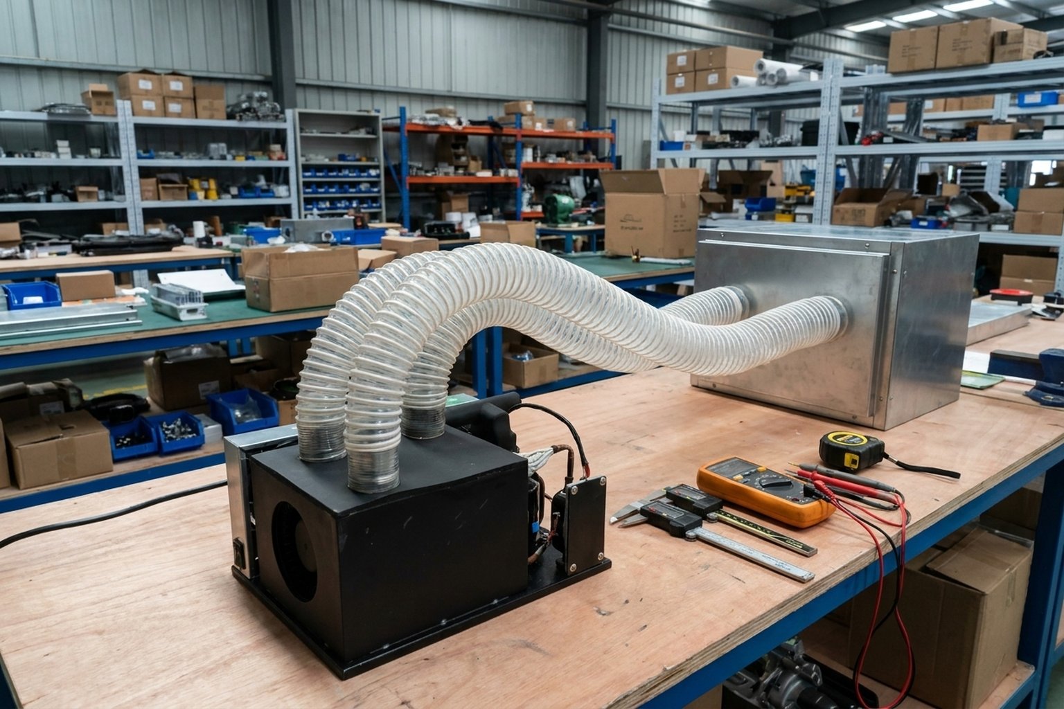
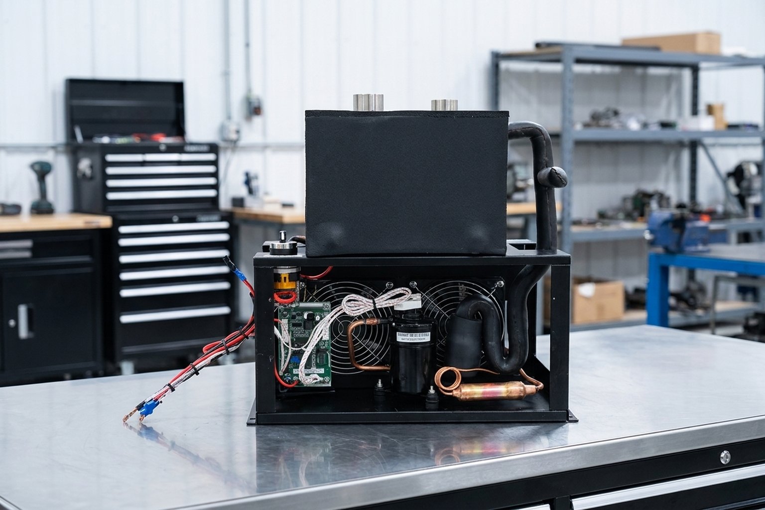
Once you have your estimated cooling requirement, you can match it to available models. The RIGID Micro DC Aircon series offers several capacity points designed specifically for enclosure cooling applications:
- 450W cooling capacity — Available in 12V (DV1910E-AC), 24V (DV1920E-AC), and 48V (DV1930E-AC) configurations. Suitable for smaller enclosures with moderate heat loads.
- 550W cooling capacity — The DV3220E-AC (24V) bridges the gap for mid-range applications.
- 700W cooling capacity — The DV2820E-AC (24V) handles heavier loads. An R290 eco-refrigerant variant (DV2820E-AC-T) is also available for applications where low-GWP refrigerant is preferred.
- 900W cooling capacity — The DV3820E-AC (24V) and DV3830E-AC (48V) serve the highest loads in this compact form factor.
For our example requiring approximately 606W of cooling, the 700W models provide adequate capacity with remaining margin. Selecting the 550W model would leave insufficient headroom, while the 900W model would be oversized for steady-state conditions but might be appropriate if future equipment additions are planned.
All models in this range weigh approximately 11 lbs (5 kg) and deliver 27.8 CFM of airflow within the enclosure. They operate on DC power directly—12V, 24V, or 48V depending on model—requiring no inverter. This is particularly valuable in battery-backed, solar-powered, or vehicle-mounted installations where DC is the native power source.
The BLDC (brushless DC) variable-speed compressor in these units adjusts its speed to match the actual cooling demand, which improves efficiency at partial loads and reduces energy consumption compared to fixed-speed alternatives.
Ambient Temperature: The Variable That Changes Everything
Cooling capacity is not a fixed number—it varies with conditions. The most critical variable is the ambient temperature outside the enclosure. As ambient temperature rises, the temperature differential the air conditioner must work against increases, and effective cooling capacity decreases.
The RIGID Micro DC Aircon series operates within a cooling temperature range of 5°C to 30°C for the conditioned space. This means the system is designed to maintain internal enclosure temperatures within this range under normal operating conditions.
When sizing, always use the worst-case ambient temperature your installation will face—not the average. If your enclosure sits in a location that reaches 50°C in summer, you must size for that peak, even if the average is 35°C. Equipment failures happen at extremes, not averages.
Key ambient considerations:
- Geographic extremes: Desert installations, rooftop locations, and engine compartments can see ambient temperatures well above 40°C.
- Microclimate effects: Enclosures near heat-generating equipment (engines, exhaust systems, other machinery) may experience local ambient temperatures far above general area temperature.
- Altitude: At high altitudes, air density decreases, reducing the effectiveness of air-cooled condensers. This is generally a minor factor below 2000m but becomes significant at higher elevations.
- Seasonal variation: Size for summer peaks, but verify the system can handle low-load winter conditions without excessive short-cycling.
Common Sizing Mistakes and How to Avoid Them
Years of field experience reveal recurring errors in enclosure cooling specification. Avoiding these pitfalls saves time, money, and equipment.
Mistake 1: Confusing Electrical Input Power with Cooling Capacity
This is perhaps the most dangerous error. If a component draws 700W of electrical power, that does not mean you need 700W of cooling. You need to cool only the waste heat—the portion of input power not converted to useful work. A motor drive drawing 700W but operating at 95% efficiency only dissipates about 35W as heat inside the enclosure (assuming the motor itself is outside). Always calculate actual heat dissipation, not nameplate power ratings.
Mistake 2: Ignoring Future Expansion
Enclosures rarely stay at their initial configuration. Additional cards, modules, or equipment get added over time. If you size exactly to current load with no margin, the first addition pushes the system beyond capacity. Build in 15-25% headroom for growth, or document the maximum additional load the cooling system can handle.
Mistake 3: Using Average Ambient Instead of Peak
As discussed above, thermal failures occur at extremes. A system sized for 35°C average ambient will be overwhelmed during a 45°C heat wave—precisely when cooling is most critical. Always size for the worst case your site will realistically experience.
Mistake 4: Neglecting Solar Load on Outdoor Enclosures
Solar radiation can easily add 200-400W to an outdoor enclosure’s heat load. Omitting this from calculations leads to chronic overheating during sunny conditions. If the enclosure is outdoors, solar load must be part of your calculation—or you must provide adequate shading.
Mistake 5: Assuming Peltier/TEC Solutions Scale Linearly
Thermoelectric coolers (Peltier/TEC devices) are simple and have no moving parts, which makes them attractive for small loads. However, their efficiency drops dramatically as cooling demand increases. For heat loads above approximately 100-150W, vapor compression systems (like the RIGID Micro DC Aircon) are typically 3-5x more energy efficient. Choosing TEC for a 500W heat load means consuming far more power for cooling than a compressor-based solution would require.
Mistake 6: Poor Airflow Planning Inside the Enclosure
Even a correctly sized air conditioner cannot cool effectively if internal airflow is blocked. Hot spots develop when cool air cannot reach heat-generating components. Ensure the enclosure layout allows the 27.8 CFM of conditioned air to circulate past all critical components. Avoid placing large obstructions directly in front of the unit’s discharge.
What DC Enclosure Cooling Is Good For—and What It Is Not
DC air conditioners in the 450-900W cooling range excel in specific applications:
Well-suited applications:
- Telecom cabinets and remote communication equipment shelters
- Battery storage enclosures (lithium-ion, lead-acid) requiring temperature management
- Industrial control panels with PLCs, drives, and power supplies
- Outdoor electronic enclosures (traffic control, monitoring stations, utility equipment)
- Vehicle-mounted electronics compartments (military, construction, mining)
- Solar-powered remote installations where DC is the native power source
- Medical device enclosures requiring stable temperature environments
Applications where this range may not be sufficient:
- Large server rooms or data center racks with multi-kilowatt heat loads (these need larger dedicated cooling systems)
- Enclosures requiring temperatures below 5°C (below the operating range of these units)
- Extremely high ambient environments above 55°C without supplemental measures
- Applications requiring redundant cooling (consider dual units or larger systems with backup)
- Very large enclosures (walk-in shelters) where 900W maximum capacity is insufficient
Understanding these boundaries helps you select the right technology for the job rather than forcing a solution into an application it was not designed for.
Refrigerant Considerations
The standard models in the RIGID Micro DC Aircon range use R134a refrigerant, which is well-established and widely supported. For applications where environmental regulations or corporate sustainability policies favor low-GWP (Global Warming Potential) refrigerants, the DV2820E-AC-T variant uses R290 (propane), a natural refrigerant with very low GWP.
R290 units may be subject to additional installation requirements in some jurisdictions due to the flammable nature of the refrigerant. Consult applicable local codes and standards for your specific installation location and application before specifying R290 units. Requirements vary significantly by region and application type.
When to Consult the Manufacturer
While this guide provides a solid starting framework, certain situations warrant direct consultation with RIGID’s engineering team:
- Unusual ambient conditions: Extreme temperatures, high humidity, corrosive atmospheres, or high-altitude installations.
- Tight space constraints: When the enclosure geometry limits mounting options or airflow paths.
- Custom voltage requirements: If your DC bus voltage does not match the standard 12V, 24V, or 48V options.
- High-reliability applications: Where failure consequences are severe (medical, military, critical infrastructure).
- Borderline sizing: When your calculated load falls between two model capacities and you are unsure which direction to go.
- Integration with existing control systems: When the cooling unit needs to communicate with a BMS, SCADA, or other supervisory system.
RIGID provides integration support for system designers and OEMs, including thermal modeling assistance, custom configuration options, and technical documentation for integration into larger systems. Reaching out early in the design process can prevent costly redesigns later.
Sizing Checklist: Putting It All Together
Use this checklist as a practical summary of the sizing process:
- Inventory all heat sources inside the enclosure. Calculate actual waste heat, not nameplate power.
- Estimate solar load if the enclosure is outdoors or exposed to radiant heat sources.
- Calculate wall conduction based on enclosure size, material, and worst-case ambient temperature.
- Sum all heat sources to get total heat load in watts.
- Add safety margin of 10-25% depending on estimation confidence and criticality.
- Select the model whose cooling capacity meets or exceeds your total with margin.
- Verify voltage compatibility with your DC power source (12V, 24V, or 48V).
- Check physical fit—the unit weighs approximately 5 kg and needs adequate mounting space plus clearance for airflow.
- Plan internal airflow to ensure conditioned air reaches all heat-generating components.
- Document assumptions so future modifications can be evaluated against the original sizing basis.
Conclusion
Sizing a DC air conditioner for an enclosure is a methodical process, not a guessing game. By quantifying your heat load from all sources, applying appropriate safety margins, accounting for worst-case ambient conditions, and selecting from the available capacity range, you arrive at a solution that protects your equipment reliably and efficiently.
The key principles are simple: know your heat load, size for the worst case, and leave room for growth. When in doubt, consult the manufacturer—it is far less expensive to get the specification right on paper than to replace failed equipment in the field.
With proper sizing, a compact DC air conditioner delivers years of reliable enclosure cooling with minimal maintenance, no inverter complexity, and energy efficiency that far exceeds thermoelectric alternatives for loads in the 450-900W cooling range.