
Enclosure Return Air Path Design Decides Whether Capacity Reaches the Hot Part
A sealed cabinet with a correctly sized air conditioner can still cook a drive at the top of the rack. The capacity calculation was right, the unit is delivering it, and the enclosure average temperature is exactly where it should be — but the component that matters is sitting in a pocket of air the cold supply never reaches.
This is an air distribution problem, and it is decided almost entirely by the return path. Where the warm air is drawn from determines where the cold air actually goes, because air will always take the shortest route between supply and return. Get that geometry wrong and the unit short-circuits its own supply back to its own intake, leaving the far corner of the cabinet untouched while the controller reports satisfaction.
This guide covers the short-circuit failure, how to place supply and return around real component layouts, when baffles earn their place, and how to verify distribution rather than assume it.
The Short Circuit Is the Default Failure
Enclosure return air path design fails in one characteristic way. A unit blows cold air in at one opening and draws warm air out at another. If those two openings are close together and nothing forces the air to travel, most of the supply goes straight back to the return without passing anything that generates heat.
What makes this failure hard to spot is that the instrument reads correctly. The unit’s return air sensor sees cold air — because it is receiving its own supply — so it satisfies quickly, cycles off, and reports a comfortable enclosure. Meanwhile:
- Components remote from the supply sit in stagnant air that only exchanges by natural convection.
- Heat concentrates at the top of the cabinet, where warm air collects and there is no forced path out.
- The unit short-cycles, because it reaches setpoint faster than the enclosure actually does.
The signature is worth memorizing: a low return air temperature combined with a hot component is short-circuiting, not overcapacity. Adding capacity makes it worse, because a larger unit satisfies its return sensor even faster and runs even less.
Placing Supply and Return Around the Load
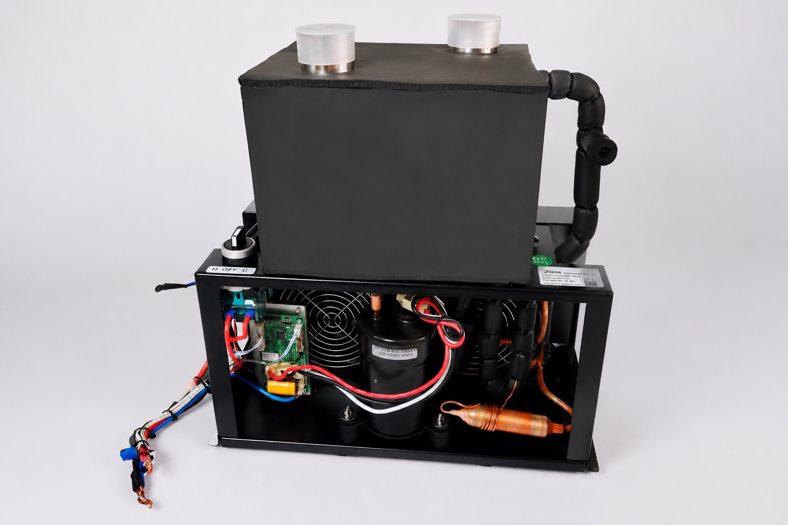 The working principle of enclosure return air path design is to make the air travel past the heat on its way from supply to return. Three arrangements cover most cabinet geometries.
| Arrangement | Supply | Return | Suits |
|---|---|---|---|
| Vertical sweep | Low, directed upward at the front of the components | High, at the opposite side | Tall cabinets with distributed load; works with natural buoyancy |
| Front-to-back | One face, across the component front | Opposite face | Shallow cabinets, component fronts facing the supply |
| Targeted supply | Ducted directly at the highest-dissipation component | Anywhere remote from supply | One dominant heat source with lower-power equipment around it |
Velocity matters as much as position. A Micro DC Aircon unit such as the 2.8 cc or 3.8 cc twin-cylinder models delivers its capacity through a finite airflow, and that airflow has a throw distance — the depth into the cabinet it can reach before losing its directed velocity and becoming diffuse. In a shallow cabinet this is irrelevant; in a deep one, a supply opening on the front face may simply not reach the back, regardless of how much capacity is available. Where throw is marginal, a short duct or deflector at the supply is worth more than additional watts.
Two rules apply regardless of arrangement:
- Separate supply and return as far as the cabinet allows. This is the single most effective change and it usually costs nothing but a decision at design time.
- Work with buoyancy rather than against it. Warm air rises, so a high return is the low-effort choice; a low return has to overcome the natural gradient and needs more velocity to do it.
The classic mistake is placing supply and return on the same face at similar heights because it simplifies the cutouts. That geometry guarantees a short circuit.
Baffles: Where They Earn Their Place
Baffles do one job in enclosure return air path design — they prevent air from taking a shortcut, forcing it along the path you intended. In enclosure work they are worth adding in three situations:
- Blocking a bypass. A gap beside or above a component set lets air slip past without doing work. Closing it is often worth more than any increase in airflow.
- Directing supply into a specific region. A simple deflector at the supply opening can turn a diffuse jet into a stream that reaches the back of the cabinet.
- Separating warm and cold zones so returning air does not mix with supply before it has been used.
Established practice in larger airflow systems is that baffles substantially improve distribution uniformity and reduce localized hot spots by preventing recirculation. The same principle scales down to a control cabinet, where a single sheet of blanking plate in the right position frequently resolves a hot spot that no amount of extra capacity would have fixed.
Baffles have a cost too: every obstruction adds pressure drop, and an enclosure fan or a unit’s internal blower has a finite pressure budget. Baffling that is too aggressive reduces total circulation while improving its direction, and the net result can be worse.
Component Layout Is Part of the Air Path
Enclosure return air path design is usually treated as something to sort out after the components are placed. Reversing that order costs nothing and prevents most distribution problems.
- Put the highest-dissipation components where supply air arrives first, not where there happens to be room.
- Keep the most temperature-sensitive components out of the return path, since that air has already collected heat from everything upstream.
- Avoid stacking heat sources vertically in the same column, where each one preheats the air arriving at the one above.
- Leave clearance in front of any device with its own fan. A device fan fighting the cabinet circulation produces a local recirculation cell rather than cooperation.
- Account for cable bundles. A dense loom is an effective air dam, and it is usually installed after the thermal design was signed off.
The last point is the one that catches production units that behaved perfectly as prototypes. Nothing about the thermal design changed; a wiring harness simply arrived in the air path.
Verifying Distribution Rather Than Assuming It
Verifying enclosure return air path design needs the right measurement, and enclosure average temperature is not it, because the failure mode is a gradient rather than an average. A short verification catches it:
- Place temperature sensors at the components you actually care about, not at the return air opening.
- Run the enclosure at full electrical load with the door closed, at the highest ambient available.
- Log until temperatures stabilize, which can take longer than expected in a cabinet with significant thermal mass.
- Compare the hottest component reading against the return air temperature. A large gap indicates poor distribution; a small gap indicates the air is genuinely circulating.
- If a gap exists, change geometry before changing capacity — move the return, add a deflector, close a bypass.
- Re-run and compare. Distribution changes usually show up immediately, whereas capacity changes show up as shorter run times.
Sensor placement in step 1 deserves a note of its own. Mounting a logger on the cabinet wall, or clipping it to a convenient rail, measures air that has already mixed. The reading that matters is at the component surface or in the air immediately entering it, because that is the temperature the component actually experiences. A cabinet can show a perfectly acceptable air temperature 100 mm away from a device that is running well above its rating.
Step 4 is the diagnostic that separates the two failure classes. A unit that is genuinely undersized shows return air temperature above setpoint with the unit running continuously. A distribution problem shows return air comfortably at setpoint with a component far above it.
How This Interacts With Unit Sizing
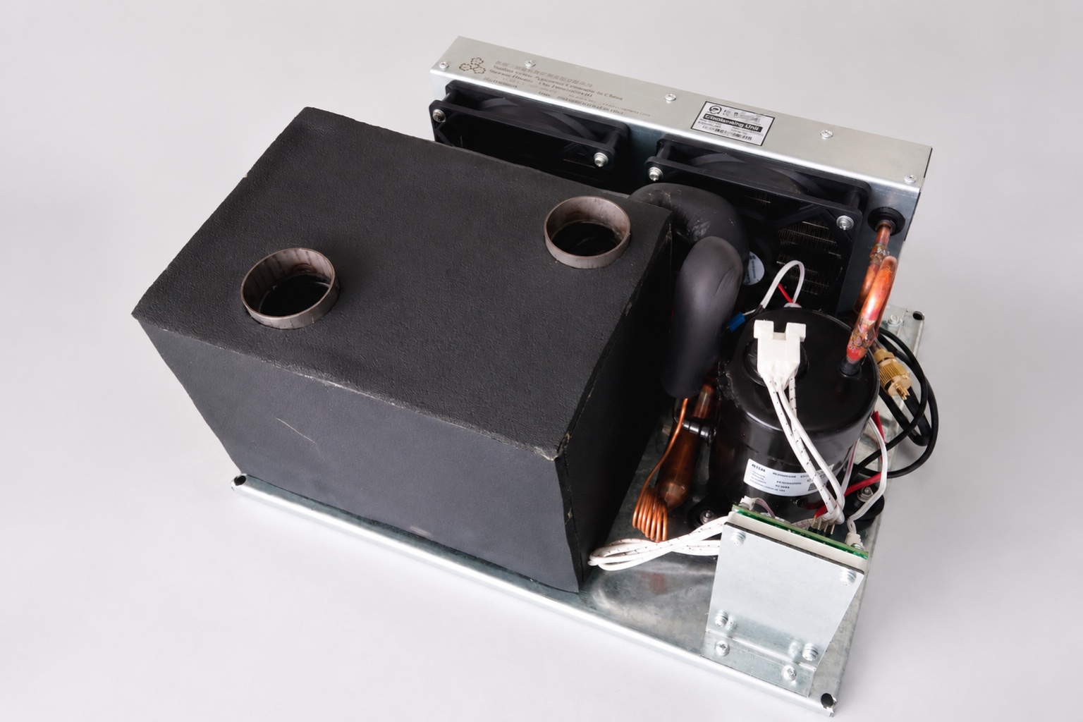 Capacity sizing and distribution are separate problems that are frequently confused, and treating one as the other wastes both money and time.
| Observation | Distribution problem | Capacity problem |
|---|---|---|
| Return air temperature | At or below setpoint | Above setpoint |
| Unit duty cycle | Short cycling | Continuous running |
| Hot component vs return air | Large gap | Small gap, both high |
| Effect of adding capacity | No improvement, or worse | Improvement |
| Effect of moving the return | Immediate improvement | Little change |
Enclosure load calculation itself is covered separately in our DC air conditioner sizing guide for enclosures. Product data for the micro DC air conditioning range, including the 2.8 cc and 3.8 cc twin-cylinder units, is on the micro DC aircon product page. Where the enclosure is in a contaminated environment and air-side cooling brings the contamination with it, a sealed loop using the DV compact liquid chiller range — DV1910E, DV1920E, DV3220E and related variants at 100–550 W — avoids the air path entirely, moving heat rejection outside the cabinet rather than pulling contaminated air through it.
If you want the air path reviewed before the cabinet is built, send the following and our engineers will comment: internal dimensions, component layout with dissipation per device, which components are temperature-critical, available faces for supply and return cutouts, whether any device has its own fan, cable routing, sealing class, and maximum external ambient. Send your cabinet layout to our engineering team.
Frequently Asked Questions
Why is one component hot when the cabinet is cold?
Almost always because supply air is short-circuiting back to the return without passing that component. Air takes the shortest available route, so if supply and return openings are close together most of the flow never reaches the far parts of the cabinet. The give-away is a low return air temperature alongside a hot component — the unit is satisfying its own sensor with its own supply. Enclosure return air path design, not capacity, is what fixes this.
Where should the return opening go?
As far from the supply as the cabinet geometry allows, and high, where warm air naturally collects. A high return works with buoyancy rather than against it and needs less velocity to be effective. Placing supply and return on the same face at similar heights is convenient for fabrication and guarantees a short circuit.
Will a bigger air conditioner fix a hot spot?
Usually not, and it can make things worse. A larger unit satisfies its return air sensor faster, so it runs for a shorter fraction of each hour, which means less total air circulated through the cabinet. If the problem is that air is not reaching the component, reducing circulation time is the opposite of what is needed. Change the geometry first and re-measure.
Do I need baffles inside a control cabinet?
Only where there is a specific bypass to close or a specific region to direct air into. A single blanking plate closing a gap that lets air slip past a component set is often more effective than any increase in airflow. Avoid over-baffling: every obstruction adds pressure drop, and beyond a point you improve direction while reducing total circulation.
How do I tell a distribution problem from an undersized unit?
Compare the hottest component temperature against the return air temperature at full load with the door closed. A large gap with the return at setpoint is a distribution problem. Both high, with the unit running continuously, is a capacity problem. The two call for opposite responses, which is why the measurement is worth taking before ordering anything.
Does component layout really matter that much?
It is part of the air path whether or not it was designed that way. Stacking heat sources vertically means each one preheats the air arriving at the one above; putting a temperature-sensitive device in the return path exposes it to air that has already collected heat from everything upstream; and a dense cable loom is an effective air dam. That last one is why production units sometimes run hotter than the prototype they were validated on.