
How a Heat Flow Meter Uses Its Cold Plate
A heat flow meter measures how well a flat specimen of insulation, foam, board or textile resists heat. The method most laboratories in North America use is ASTM C518. The specimen sits between a hot plate and a cold plate, each held at a controlled temperature, and heat flux transducers measure the heat flowing through it once conditions are steady. From the heat flux, the temperature difference and the thickness, the instrument calculates thermal conductivity and thermal resistance.
The cold side is where cooling equipment comes in. A heat flow meter can only produce a trustworthy result when both plates hold their temperatures steadily for long enough to reach equilibrium, and the cold plate depends on a coolant supply to do that.
This guide explains what test temperatures ask of the cooling loop, estimates the heat involved, shows why stability matters more than capacity, and covers where a compact liquid chiller module fits and where its limits are.
Test Temperatures and What They Ask of Cooling
Heat flow meter tests are usually specified by a mean specimen temperature and a temperature difference across the specimen. The cold plate temperature follows from those two numbers.
| Mean temperature | Temperature difference | Cold plate | Hot plate |
|---|---|---|---|
| 24 °C | 22 K | 13 °C | 35 °C |
| 10 °C | 20 K | 0 °C | 20 °C |
| −5 °C | 20 K | −15 °C | 5 °C |
| 40 °C | 20 K | 30 °C | 50 °C |
These are illustrative combinations. Product standards and customer specifications set the actual mean temperatures and differences, and many insulation programs run several mean temperatures to show how conductivity changes. The table makes one point clear: the same instrument can need a cold plate well above room temperature for one test and below freezing for another.
Temperature difference is a trade-off. A larger difference gives a stronger heat flux signal but moves the plates further from the mean, which matters for materials whose conductivity changes with temperature. Test programs balance the two, and the cooling loop has to follow whatever the program chooses, including the coldest plate temperature at the lowest mean.
Two Ways Instruments Control the Cold Plate
Before choosing coolant temperatures, find out how your instrument controls its plates. The answer changes what the cooling loop has to do.
| Architecture | What the coolant does | Coolant temperature needed |
|---|---|---|
| Direct coolant control | Coolant flowing through the plate sets the plate temperature | Close to the plate set point, very stable |
| Thermoelectric plate control | Thermoelectric elements set the plate temperature and reject heat into the coolant, which acts as a heat sink | The supply temperature the manufacturer specifies, which need not be colder than the plate |
| Coolant plus trim heaters | Coolant cools, heaters trim the plate up to set point | Colder than the plate by the margin the manufacturer specifies |
This is why a single rule such as “the coolant must be colder than the cold plate” is not safe. With thermoelectric plate control, a moderate, stable coolant supply can serve plate temperatures both above and below it. The instrument’s own installation requirements for coolant temperature, heat rejection, flow and pressure are the real specification, and they differ between models.
How Much Heat the Cold Side Removes
The heat that flows through the specimen itself is small. Most of the cooling duty comes from elsewhere. The example below uses assumed values for illustration.
| Heat source | Assumption | Heat |
|---|---|---|
| Heat through the specimen | Conductivity 0.035 W/m·K, 25 mm thick, 0.36 m² plate, 22 K difference | About 11 W |
| Instrument plate control | If the plates use thermoelectric elements or trim heaters, their power also reaches the coolant | Can be tens to hundreds of watts; check the instrument documentation |
| Chamber and plate edge gains | Room and enclosure heat reaching the cold side | About 20 W |
| Hoses and fittings | Short insulated runs at a cold plate temperature below room | About 10 W |
 The estimate makes the sizing picture clear. For a heat flow meter, the specimen is rarely what decides the cooling capacity. How the instrument controls its plates, and how well the chamber and hoses are insulated, matter more. Check the instrument documentation for the heat rejected to the coolant at your coldest and warmest plate temperatures.
Chamber design changes the numbers noticeably. A well-sealed instrument with guarded plates and good edge insulation loses little heat to the room, while an open or poorly sealed stack can add more heat at the cold side than the specimen does. When comparing instruments or modifying one, the heat rejected to the coolant is worth measuring directly: log coolant supply and return temperatures and flow at a steady test condition.
Stability Matters More Than Capacity
A heat flow meter works at steady state. The instrument waits until plate temperatures and heat flux readings stop changing within set limits before it records a result.
- Coolant temperature swings slow every test, because the instrument keeps waiting for equilibrium that the coolant keeps disturbing.
- Periodic swings from on-off compressor cycling can show up as oscillation in heat flux readings, especially on thin or conductive specimens.
- Many instruments control plate temperatures with thermoelectric elements and use the coolant as a heat sink at a temperature the manufacturer sets; they still need that sink to be stable.
- Flow changes matter too. A loop whose flow drifts as the coolant cools or a filter loads changes how much heat the plate can reject.
Temperature stability at the coolant supply is what the instrument sees, so measure it there over a full test length rather than relying on a chiller’s display. A small data logger on the supply line for an afternoon shows whether swings line up with slow equilibrium or oscillating flux readings.
Our guide to chillers for analytical instruments covers the same stability-first logic for other laboratory equipment.
How Cold the Coolant Should Run
The right coolant temperature depends on how the instrument controls its cold plate.
- If coolant temperature directly sets the cold plate, the coolant must sit close to the plate set point and be very stable.
- If the instrument sets the plate with thermoelectric elements, supply coolant at the temperature, flow and pressure the manufacturer specifies; it does not need to be colder than the plate.
- If the instrument cools with coolant and trims the plate with heaters, the coolant must be colder than the plate by the margin the manufacturer specifies.
- Below the room’s dew point, condensation forms on cold surfaces. Follow the instrument’s guidance on dry purge or enclosure sealing for sub-ambient tests.
- Avoid coolant temperatures colder than the instrument allows, even if the circulator can supply them.
If the instrument documentation does not state the required coolant temperature, flow and heat rejection, ask the manufacturer rather than guessing. The wrong supply temperature either starves the plate control of authority or wastes cooling and raises condensation risk.
Connecting the Cooling Loop
- Use the fluid the instrument manufacturer approves, at a concentration with margin below the coldest coolant temperature.
- Keep hoses short and insulated, and route them so condensate cannot reach the instrument electronics.
- Confirm the flow rate and maximum pressure the cold plate allows, and check them with the coolant at operating temperature.
- Filter and maintain the coolant; plate channels are often small and sensitive to deposits.
- Use a coolant selection that stays stable over long running times. Our lab chiller coolant selection guide compares options.
Plan the hose route before the instrument is installed. Heat flow meters are often placed against a wall or in a cabinet, and long hose runs added later to reach a cooling unit elsewhere in the room add heat, pressure drop and condensation points that are easy to avoid at the start.
Running Several Mean Temperatures in One Program
Many heat flow meter programs step through several mean temperatures on the same specimen to show how conductivity varies. That puts extra demands on the cooling loop.
- Order the steps so the cold plate moves gradually, rather than jumping between the warmest and coldest points.
- Allow for the time the coolant loop needs to settle at each new temperature, not just the plates.
- Check that the coolant range covers the coldest and warmest cold plate points in the program before starting.
- Watch for condensation when a step takes the cold plate below the dew point for the first time in the sequence.
Running the coldest steps last in the day, and returning the plates above the dew point before opening the stack, keeps moisture off the specimen and plates.
Where a Compact Liquid Chiller Module Fits
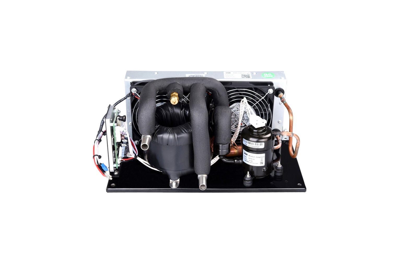
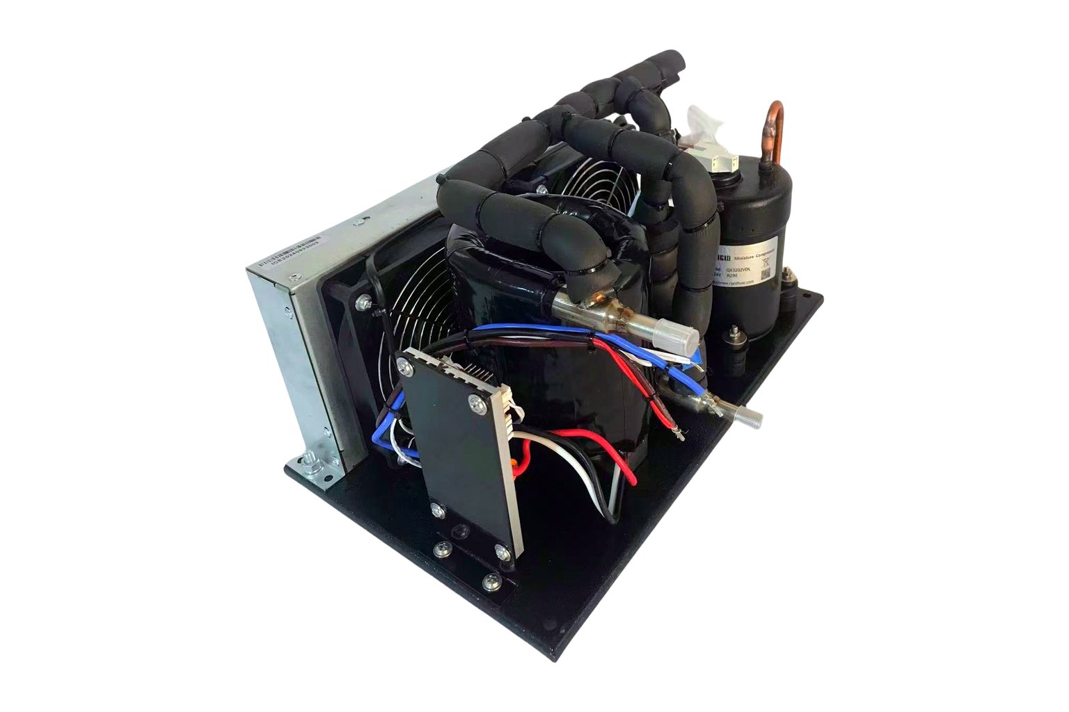 A compact liquid chiller module is most useful to instrument builders and laboratories integrating cooling into a heat flow meter system, rather than as a separate benchtop circulator. It puts a controlled cold source inside or beside the instrument cabinet. Short loops also help stability, because less coolant sits in hoses exposed to room temperature.
RIGID’s Compact Liquid Chiller line (DV series) is listed at 100 to 550 W of cooling capacity, with a listed temperature range of ±20 °C, 12V, 24V or 48V DC supply, and R134a or R290 refrigerant. It is offered with plate, coaxial, stainless steel coil and copper coil heat exchanger structures, such as the DV1920E-C coaxial version at 24V. Pump flow, pump head and the test conditions behind the capacity figures are not listed, and the product line includes configurations described with an external pump as well as integrated circulation, so confirm the pump, reservoir, controller and power supply for the specific version. A DC module also needs a suitable power supply when it is not built into DC-powered equipment.
How the listed range applies depends on the architecture. Where coolant sets the cold plate directly, the range limits which plate temperatures the module can serve, and plate or coolant temperatures beyond +20 °C, or any duty that needs the coolant heated, need other equipment. Where thermoelectric elements control the plates, what matters is whether the module can hold the manufacturer’s specified supply temperature while rejecting the instrument’s stated heat load with the required flow and pressure. Check those numbers against the specific module version rather than comparing plate temperatures with the module range.
Sizing Checklist
- List every mean temperature and temperature difference in your test program, and the cold plate temperature each one needs.
- Get the heat rejected to the coolant at those plate temperatures from the instrument documentation.
- Check that the coolant temperature range covers every cold plate point, including margin if the instrument trims its plates.
- Confirm capacity at the coldest coolant temperature, with margin for room conditions. Our guide to small chiller sizing and set point derating explains why capacity falls as set points drop.
- Check flow, pressure and fluid compatibility against the cold plate specification.
- Verify stability over a full test: log coolant temperature and heat flux readings together.
Keep the sizing notes with the instrument records. When the test program changes, for example adding a colder mean temperature for a new insulation product, the same notes show quickly whether the existing cooling loop still covers it.
Common Mistakes
- Sizing heat flow meter cooling for the specimen heat and ignoring plate control power.
- Choosing cooling by capacity and ignoring the stability the steady-state method needs.
- Running sub-ambient tests without dry purge or condensation control.
- Assuming one cooling source covers every test point, including cold plates above room temperature.
- Using coolant colder than the instrument allows.
- Neglecting coolant filtration for small plate channels.
If you are integrating cooling into a heat flow meter or thermal test system, send us your cold plate temperature range, the heat rejected to coolant, flow and pressure limits, supply voltage and space available, and our engineers will help assess the cooling loop. Send your heat flow meter cooling details to our engineering team.
Frequently Asked Questions
Why does a heat flow meter need a chiller?
The cold plate has to be held at a steady temperature below the hot plate, often at or below room temperature. A cooling loop provides the cold source that makes those plate temperatures possible and stable.
How much cooling does a heat flow meter need?
The heat through the specimen is usually small, around 11 W in the worked example. Plate control power, chamber gains and hoses usually matter more, so check the instrument’s documented heat rejection at your plate temperatures.
What coolant temperature should a heat flow meter run?
It depends on how the instrument controls the cold plate. If the coolant sets the plate directly, run it close to the plate set point. If the instrument controls the plate with thermoelectric elements, supply coolant at the temperature the manufacturer specifies, which need not be colder than the plate; if it uses coolant plus trim heaters, run the coolant colder by the specified margin.
Why do my heat flow meter tests take so long to settle?
Common causes are coolant temperature swings, flow changes, condensation and poorly insulated hoses. A stable coolant supply usually shortens the time to reach equilibrium. Logging coolant supply temperature during a test shows whether swings line up with slow settling.
Can one chiller cover every ASTM C518 test point?
It depends on the architecture. Where coolant sets the plate directly, the coolant range must reach every cold plate temperature in the program, and plate temperatures beyond +20 °C are outside the listed range of RIGID’s DV-series modules. Where thermoelectric elements control the plates, one stable coolant supply at the manufacturer’s specified temperature can serve the whole program if it carries the stated heat load.
Does the heat flow meter method require a specific cooling fluid?
The method does not usually dictate the fluid, but the instrument manufacturer does. Use an approved fluid at a concentration with margin below the coldest coolant temperature. Keep the fluid clean and replace it on a schedule so small plate channels stay clear.