
Why Every Laser Chiller Module Conversation Starts with a Failed Fan
The pattern is remarkably consistent. A laser marking or engraving system ships with fan-based cooling — heatsinks, axial fans, maybe a thermoelectric cooler (TEC) stage. It works in the test lab at 22 degrees ambient. It works during the first few weeks on the factory floor. Then summer arrives, or the system moves to a facility without climate control, or the duty cycle increases from intermittent marking to continuous engraving. The laser diode temperature drifts above 26 degrees. Output power drops. Beam quality degrades. The laser starts cycling on thermal protection. And someone begins searching for a compressor-based chiller module.
This is not a failure of the fan — it is a failure of the thermal design assumption. Fan-based cooling can only move heat from the laser source to the surrounding air. If the surrounding air is already warm, or if the heat load exceeds the fan-heatsink assembly’s capacity to maintain the required temperature differential, no amount of airflow will solve the problem. The fan cannot cool below ambient temperature. A compressor-based chiller module can.
This guide explains the thermal boundary where passive cooling stops working for laser systems, why that boundary matters for laser marking and engraving applications specifically, and what a compressor-based chiller module needs to deliver to solve the problem reliably.
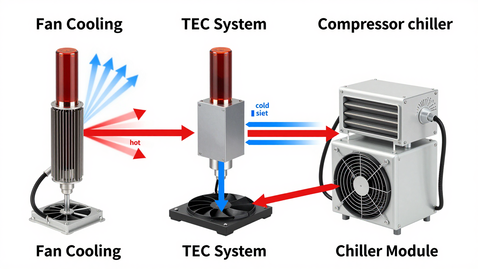
The Physics: Why Fans Cannot Cool Below Ambient
A fan-heatsink assembly transfers heat through forced convection. The heatsink absorbs heat from the laser diode (or its mount), and the fan moves air across the heatsink fins to carry that heat away. The rate of heat transfer depends on the temperature difference between the heatsink surface and the incoming air, the surface area of the heatsink, and the airflow velocity.
The critical limitation is that forced convection can only transfer heat from a warmer surface to cooler air. The heatsink temperature will always be higher than the air temperature — that differential is what drives heat transfer. As the heat load increases or the ambient temperature rises, the heatsink temperature must rise proportionally to maintain the heat transfer rate. At some point, the heatsink temperature exceeds the laser diode’s maximum operating temperature, and the system enters thermal runaway or thermal protection shutdown.
For a typical fiber laser marking system generating 500 W of waste heat at the diode module, a well-designed fan-heatsink assembly can maintain the diode junction temperature below 26 degrees when ambient air is below approximately 20 to 22 degrees. Above that ambient threshold, the thermal margin disappears. At 30 degrees ambient — a common summer factory floor temperature — the same system may see diode temperatures of 32 to 35 degrees, well above the optimal operating range.
Thermoelectric Coolers: The Halfway Solution
Thermoelectric coolers (TECs or Peltier devices) can cool below ambient temperature — they move heat from a cold side to a hot side using electrical current through a semiconductor junction. Many laser systems use TECs as a first upgrade from pure fan cooling. However, TECs have fundamental efficiency limitations that make them problematic for sustained laser cooling above approximately 100 to 200 W of heat load.
The coefficient of performance (COP) of a TEC at a 20 degree temperature differential is typically 0.5 to 1.5 — meaning the TEC consumes 1 to 2 watts of electricity for every watt of heat it moves. At a 40 degree differential, COP drops below 0.5. A TEC cooling a 500 W heat load at a 20 degree differential consumes 500 to 1,000 W of electricity and generates 1,000 to 1,500 W of total waste heat on its hot side — heat that must still be removed by a fan-heatsink assembly. The TEC solves the below-ambient problem but creates a larger total heat rejection problem.
By contrast, a vapor-compression chiller module (using a DC compressor, evaporator, condenser, and refrigerant) achieves COP values of 2.0 to 3.5 at the same temperature differential. It moves 2 to 3.5 watts of heat for every watt of electricity consumed. For the same 500 W heat load, the total waste heat (heat load plus compressor power) is approximately 650 to 750 W — less than half of the TEC’s waste heat burden. The compressor-based approach is thermodynamically superior at any heat load above approximately 100 W.
Where the Thermal Boundary Falls for Laser Marking Systems
The transition point from passive to active cooling depends on three variables:
- Heat load — the waste heat generated by the laser diode and its driver electronics
- Ambient temperature — the air temperature surrounding the laser system
- Required diode temperature — typically below 25 to 26 degrees for fiber lasers, with tighter tolerances for wavelength-sensitive applications
| Heat Load (W) | Max Ambient for Fan Cooling | Max Ambient for TEC | Max Ambient for Compressor Chiller |
|---|---|---|---|
| 100 | 28-30 C | 38-40 C | 45+ C |
| 300 | 24-26 C | 32-35 C | 45+ C |
| 500 | 20-22 C | 28-30 C | 45+ C |
| 1,000 | 18-20 C (impractical) | 24-26 C (high power consumption) | 40-45 C |
The compressor-based chiller module maintains its cooling capability across the full range of ambient temperatures encountered in real-world manufacturing environments — including facilities in tropical climates, non-air-conditioned workshops, and outdoor installations. This is the fundamental engineering reason for choosing compressor-based cooling: it decouples laser performance from ambient conditions.
What a Laser Chiller Module Must Deliver
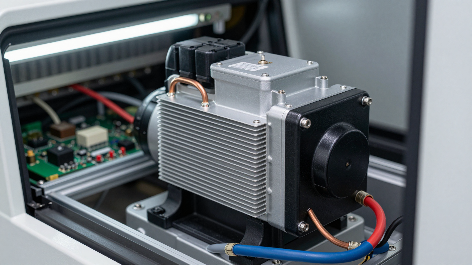
A chiller module for laser integration is not a standalone chiller unit with a water tank and pump. It is a sub-system — a compact compressor-based cooling module designed to be embedded into the laser equipment by the OEM. The requirements are specific and non-negotiable for successful laser integration.
Temperature Stability
Laser diode wavelength shifts approximately 0.3 nm per degree Celsius of junction temperature change for typical 1,064 nm fiber lasers. For marking applications, this may be acceptable within a 2 to 3 degree window. For precision engraving, spectroscopy, or medical laser applications, the window narrows to plus or minus 0.5 degrees or tighter. The chiller module must deliver temperature stability within the application’s tolerance — not just average temperature, but peak-to-peak variation during steady-state operation.
Low Vibration
Compressor vibration can degrade beam quality in precision optical systems. A rotary DC compressor generates less vibration than a reciprocating compressor, and rubber isolation mounts further attenuate transmission to the laser structure. For laser marking on moving workpieces, compressor vibration is typically not a concern. For stationary high-precision engraving or medical applications, vibration specification matters and should be verified against the optical system’s sensitivity.
Compact Form Factor
The chiller module must fit within the laser equipment’s enclosure — not beside it, not behind it, inside it. This eliminates standalone chillers connected by external hoses and requires a module small enough to integrate into the equipment’s existing volume. DC compressor-based modules achieve this through miniaturization that is not possible with conventional AC compressor technology.
DC Power Compatibility
Many laser marking systems operate from DC power buses internally. A chiller module that requires AC power forces the OEM to add an inverter or route a separate AC line — adding cost, complexity, and potential EMI issues. A DC-powered chiller module connects directly to the laser system’s existing power supply, simplifying the integration and eliminating power conversion losses.
Condensate Management
Any cooling system that operates below the dew point temperature will generate condensation. In a laser system, condensate on optical surfaces is catastrophic. The chiller module must include a condensate drain and the integration must route condensate safely away from all optical and electronic components. For applications where the cooling target is above the typical dew point (15 to 18 degrees in most environments), condensation is less of a concern — but the system design should account for worst-case humidity conditions.
Air Cooling vs. Liquid Cooling Chiller Modules
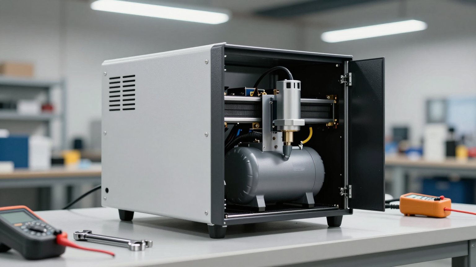
Chiller modules for laser applications come in two heat-transfer configurations:
Air-cooled modules use a fan-driven evaporator to cool air directly, which is then directed over the laser components or through a sealed enclosure. These are simpler to integrate (no plumbing), lighter, and suitable for applications where the heat source is distributed across a volume rather than concentrated at a point.
Liquid-cooled modules circulate coolant (water or water-glycol) through a closed loop that includes a heat exchanger at the laser diode mount. These provide more precise temperature control at the point of heat generation and are preferred for high-power lasers where the heat source is concentrated and the temperature tolerance is tight.
For laser marking systems in the 200 to 1,000 W heat load range, both approaches are viable. Air-cooled modules are typically chosen for lower-power marking systems where integration simplicity is prioritized. Liquid-cooled modules are chosen for higher-power systems or applications demanding tighter temperature stability.
Common Field Questions
At what power level should I switch from fan cooling to a chiller module?
There is no universal threshold — it depends on your ambient temperature requirement. If your laser system must operate reliably at 35 degrees ambient, a chiller module becomes necessary at heat loads as low as 200 to 300 W. If your system only operates in climate-controlled environments at 22 degrees, fan cooling may suffice up to 500 W or more. The deciding factor is not the heat load alone but the heat load relative to the ambient-to-target temperature differential.
Will compressor vibration affect my laser beam quality?
Modern DC rotary compressors generate vibration levels that are below the sensitivity threshold of most laser marking and engraving systems. For ultra-precision applications (interferometry, high-resolution medical imaging), verify the compressor’s vibration specification against your optical system’s requirements. Vibration isolation mounts between the chiller module and the laser structure provide additional attenuation.
How do I size the chiller module for my laser system?
Start with the total waste heat — laser diode waste heat plus driver electronics waste heat plus any other heat sources in the enclosure. Add a 20 to 30 percent margin for thermal safety. Match this to the chiller module’s cooling capacity at your maximum expected ambient temperature. A module rated for 500 W cooling at 25 degrees ambient may deliver only 350 to 400 W at 40 degrees ambient — always check the capacity at your worst-case condition, not the headline number.
Can I use a standard water chiller instead of an embedded module?
You can, and many laser integrators do. But a standalone water chiller sits outside the equipment, requires hose connections, adds floor space, and creates a visually and mechanically less integrated product. For OEMs building a commercial laser product, an embedded chiller module delivers a cleaner, more compact, and more professional result. For one-off lab setups, a standalone chiller is often the faster path.
Integration Support
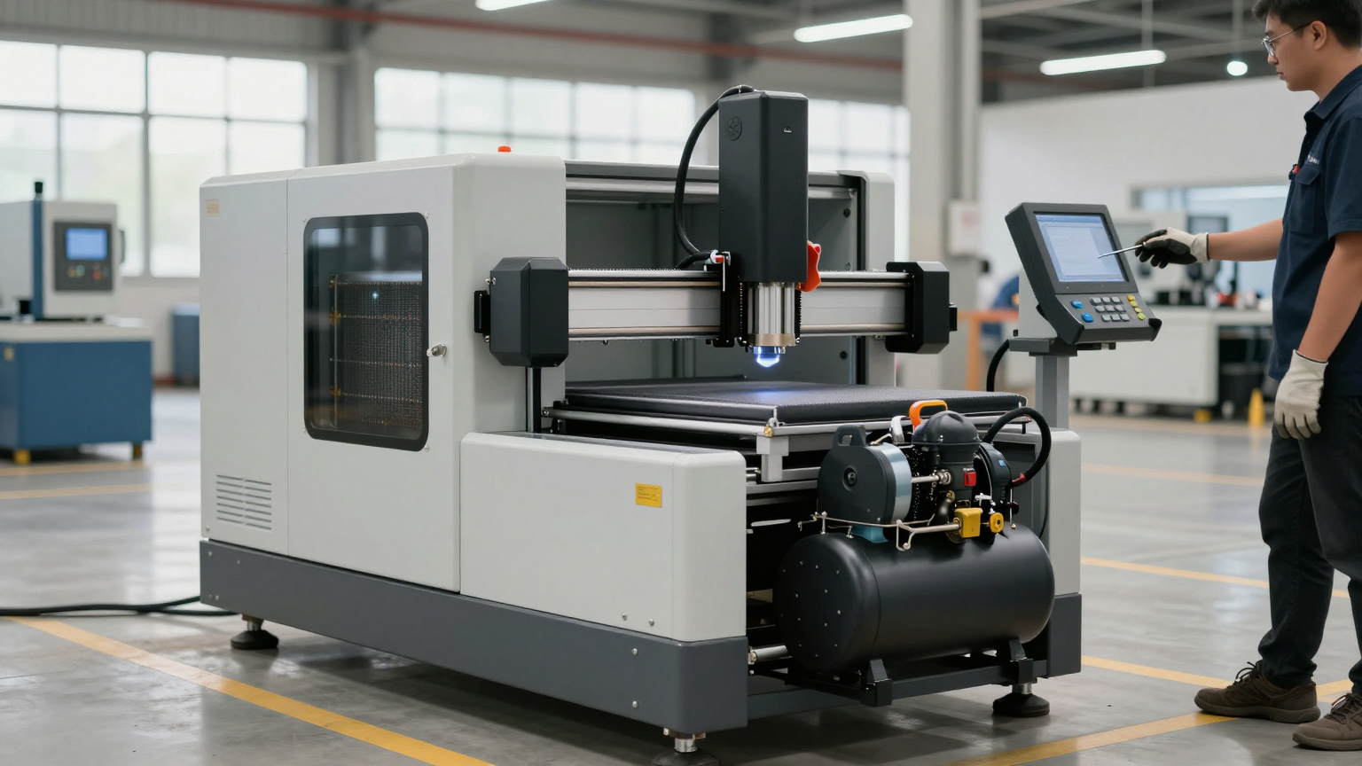
Laser thermal management is application-specific — the heat load profile, ambient range, temperature tolerance, vibration sensitivity, and available volume vary across laser types and use cases. If your laser system requires embedded compressor-based cooling and your current thermal design is reaching its limits, the Rigid engineering team can evaluate the application. The Rigid Micro DC Aircon module is a compact, DC-powered, refrigerant-pre-charged cooling sub-system designed for OEM integration into laser equipment, electronics enclosures, and precision thermal management applications.
The fan failed because the physics demanded more than convection could deliver. The chiller module succeeds because vapor compression changes the thermodynamic equation — it moves heat against the temperature gradient, holding the laser diode at its optimal temperature regardless of what the factory floor thermometer says. That is not a feature. It is the reason the technology exists.