
A Liquid Chiller Is Half the System — the Loop Is the Other Half
The specification says 550 W of cooling and 5 L/min of flow. The installation delivers noticeably less of both, and nothing is broken.
What happened is that the numbers on a liquid chiller datasheet describe the machine, not the machine plus your plumbing. Cooling capacity is measured at the unit. Flow is measured into an open pipe. Between that measurement and your equipment sits a circuit of tubing, bends, fittings, and internal passages — and every one of them takes something back.
This is the half of the system nobody specifies. It is also the half that explains most of the gap between the brochure and the bench.
Pressure Drop Is Flow You No Longer Have
A pump does not deliver a fixed flow. It delivers a flow that depends on how hard it is pushing, and that relationship is the pump curve: high flow at low pressure, falling as resistance rises.
Your circuit has a resistance too, and it rises with the square of flow. Where the two curves cross is your actual operating point — not the headline figure on either.
The practical consequence is that a pump quoted at 10 L/min may deliver 4 L/min into a real load, and both numbers are honest. A vendor who publishes a curve is giving you more useful information than one quoting a larger single number.
What contributes resistance, in rough order of size:
- The load itself. Narrow passages inside a laser head, a cold plate, or a jacketed vessel usually dominate everything else combined.
- Tube bore. Resistance scales steeply with internal diameter — going one size down costs far more than the size change suggests.
- Quick-disconnects. Convenient, and frequently the second-largest restriction in a small circuit. The bore inside the coupling is what matters, not the hose it fits.
- Bends and length. Each contributes; sharp bends contribute more than gentle ones.
- Filters and strainers. Small when clean, unbounded when not.
For the wider architecture around the loop — reservoir, control, and where the chiller sits relative to the load — see the notes on liquid chiller system design.
Sizing the Tube
Two rules cover most small-circuit work.
Match or exceed the port size. If the chiller and the load both have 10 mm ports, do not connect them with 6 mm tubing because it was on the shelf. The narrow section sets the resistance for the whole run.
Keep velocity sensible. Roughly 1–2 m/s is a reasonable target for water in small circuits. Below that, air pockets are harder to sweep out; above it, pressure drop climbs quickly and noise appears.
Where a longer run is unavoidable, increasing the bore is far more effective than increasing the pump. Resistance falls sharply with diameter, so one size up on a long run can recover more flow than a larger pump would — and it costs less.
Fittings, and the Part That Leaks
Small liquid circuits fail at joints, not in the middle of tubes.
Barbed fittings with clamps are cheap and reliable if the tube is the right size for the barb and the clamp is positioned over it. They are also the most commonly assembled wrong.
Compression and push-fit are quicker and tolerate repeated disconnection better, at higher cost.
Quick-disconnects earn their place where the loop genuinely has to be parted often. Two cautions: choose a dry-break type if you do not want a spill each time, and check the internal bore, because a coupling that fits 10 mm hose may have a much smaller passage inside.
Mixed metals matter. A brass fitting in an aluminum circuit with conductive fluid is a galvanic cell. Keeping the fluid clean and non-conductive is the main defense; where mixed metals are unavoidable, an inhibited fluid is worth the cost.
Filling and Purging: The Step That Gets Skipped
Air trapped at a high point restricts flow permanently and will not clear itself. It is one of the most common causes of a circuit that appears undersized.
A sequence that works:
- Flush the new circuit once with clean water and discard it. New tubing and components carry manufacturing residue — cutting oil, swarf, mold release — and it all ends up at the filter otherwise.
- Fill slowly with the highest point open, so displaced air has somewhere to go.
- Run the pump briefly, then top up. The level will drop as air works out of the load.
- Repeat until the level stops falling.
- Only then trust any flow or temperature reading.
If the layout has an unavoidable high point, put the fill port there. Fighting an air lock later is far harder than preventing one now.
Laser heads are the application where flow and line losses matter most, because the tube specifies a minimum flow of its own; that case is covered in chiller selection for laser cooling.
Insulate Whenever You Run Below Ambient
Fluid colder than the room picks up heat along every meter of tubing, and the loss scales with the temperature difference.
At a 15 °C setpoint in a 22 °C room, the gain is small. At −10 °C it is four times larger, and on a few meters of bare tube it can amount to tens of watts — a meaningful fraction of a small load.
Two further reasons to insulate. Uninsulated cold lines sweat, and the condensate lands on whatever is beneath them. And the failure this produces is deceptive: the chiller reads its setpoint correctly while the instrument runs warm, and adding capacity does not help because the heat is entering between the two.
Insulate both the supply and the return. The return is warmer but still usually below ambient.
Reading the Symptoms
| What you see | Where the fault is | What to check |
|---|---|---|
| Chiller reaches setpoint, load stays warm | Loop — flow | Filter, air lock, tube bore, quick-disconnect bore |
| Correct at the chiller, warm at the load | Loop — heat gain | Line length and insulation |
| Chiller runs continuously, loses ground | Machine — capacity | Capacity at your setpoint, condenser, ambient |
| Flow fell over months | Loop — fouling | Filter, biofilm, scale from the wrong fill water |
| Level keeps dropping | Loop — leak or evaporation | Joints first, then the reservoir cap |
| Noise or bubbling in the line | Loop — air or velocity | Purge again; check velocity is not excessive |
The first two rows are the ones worth separating carefully, because both look like “not enough cooling” and neither is fixed by a bigger machine.
A Worked Circuit
Numbers make the trade-offs concrete. Take a 400 W load to be held at +15 °C, with the liquid chiller sitting two meters away under a bench.
Required flow. For a 3 °C rise across the load, 400 ÷ (69.7 × 3) ≈ 1.9 L/min. Call it 2 L/min with a little margin.
Where the resistance sits. The load’s own passages are quoted by its manufacturer at a given pressure for that flow — usually the largest single term. Four meters of tubing round trip adds its share, four elbows add theirs, and a pair of quick-disconnects add a surprising amount if their internal bore is smaller than the hose.
The bore decision. At 2 L/min, 8 mm internal bore gives a velocity near 0.7 m/s — comfortable. Drop to 6 mm and velocity rises to about 1.2 m/s with noticeably higher resistance; drop to 4 mm and it becomes the dominant restriction in the whole circuit, ahead of the load.
The check that settles it. Add the load’s stated pressure drop to an estimate for the tubing and fittings, find that total on the pump curve, and read the flow. If it falls below the 2 L/min the calculation asked for, the cheapest fix is almost always a larger bore or a shorter run — not a larger machine.
The point of working it through is that every one of those decisions is made once, at installation, and then lived with for years. An afternoon spent on bore and routing buys performance that no amount of later adjustment recovers.
Fluid Choice Belongs to the Loop
The fluid is a component, not a top-up.
Above about +5 °C, distilled or deionized water. It carries more heat per degree than anything else practical and pumps easily. Not tap water — mineral scale deposits on the heat exchanger with every thermal cycle and cannot be removed once formed.
Below that, a water/glycol mixture at the minimum concentration your setpoint requires. Glycol carries less heat and is markedly more viscous when cold, so both capacity and flow fall. Using more than necessary costs performance without adding protection you need.
Check compatibility before changing fluid type on an existing loop. Hose material that is fine with water may swell or harden in glycol, and a joint that sealed at room temperature can weep once the material has stiffened at −20 °C.
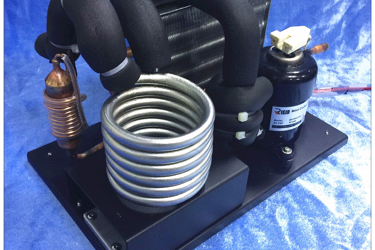
The two most common formats are compared in more detail on the plate liquid chiller and copper coil chiller pages.
Matching the Chiller Format to the Loop
Compact liquid chillers come in several heat exchanger formats, and the choice interacts with the circuit rather than being purely about capacity.
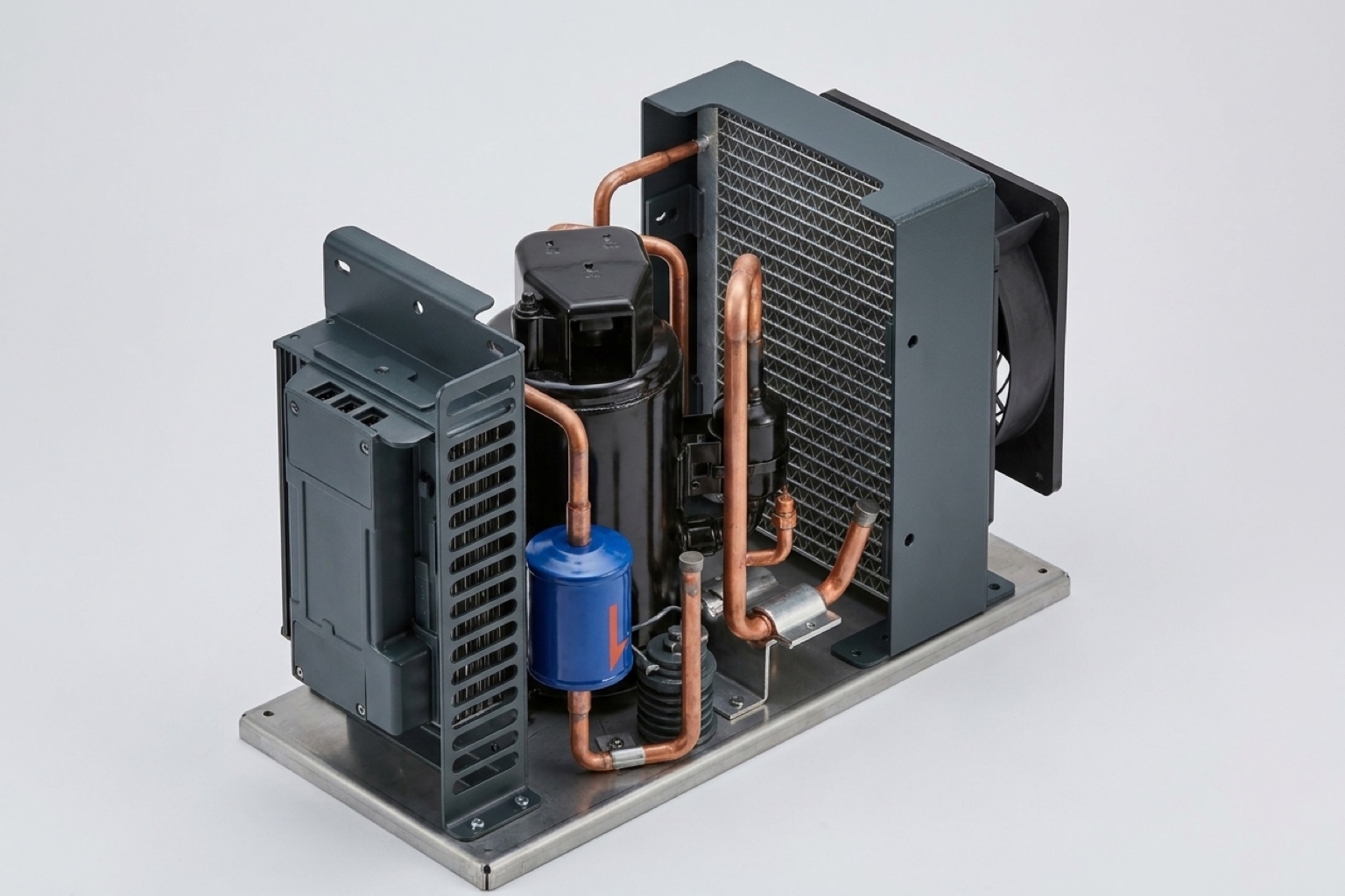
The DV series covers this band at 100–550 W across six structures — plate (DV1910E-P and siblings), coaxial (DV1910E-C), stainless steel coil, copper coil, mini water chiller, and direct expansion — on 12 V, 24 V or 48 V with R134a or R290, over a ±20 °C range. A plate unit measures around 330×200×138 mm, which is the sort of envelope that decides whether it fits under a bench or inside a machine.
Two selection notes that relate to the loop. Coil-type exchangers generally tolerate less-than-perfect fluid better than tight plate passages do. And the format affects the chiller’s own internal pressure drop, which is part of the resistance your pump sees.
The compact liquid chiller range covers all six formats. Which one suits an installation depends on the fluid, the passage sizes in your load, and the space available as much as on the watts.
If your measured flow is well below what the specification implied, the fastest way to settle it is to send the circuit rather than guess. Contact the RIGID engineering team with tube bore, total run length, fitting types, and the load’s stated pressure drop, and ask where the operating point actually falls on the pump curve.
Frequently Asked Questions
Why is my flow lower than the specification?
Because the specification is measured into an open pipe and your circuit has resistance. The load’s internal passages usually dominate, followed by tube bore and quick-disconnect bore. Compare against a pump curve rather than a single figure.
Will a bigger pump fix low flow?
Sometimes, but increasing tube bore is usually more effective and cheaper, because resistance falls steeply with diameter. Check for a blocked filter or an air lock first — both are free to fix.
How do I clear an air lock?
Refill with the highest point open, run the pump briefly, top up, and repeat until the level stops dropping. Air will not work its own way out of a high point.
Do I need to insulate the lines?
Whenever the fluid runs below ambient. The heat picked up along the run is real, it grows as the setpoint falls, and uninsulated cold lines also drip onto whatever is underneath.
Can I use tap water for a short period?
For a commissioning run of a few hours, with a full drain afterward, the harm is limited. Left in place, scale begins forming on the heat exchanger from the first thermal cycle and is effectively permanent.
Summary
A liquid chiller’s published numbers describe the machine; your results depend on the circuit you connect it to. Flow is set by where the pump curve crosses your circuit’s resistance, and that resistance is dominated by the load’s internal passages, the tube bore, and the quick-disconnects rather than by anything on the datasheet. Size the tube to match the ports rather than what is on the shelf, purge the air properly before trusting any reading, insulate whenever the fluid runs below ambient, and fill with distilled water or the minimum glycol your setpoint requires. When performance disappoints, separate the two failure modes first: a machine working hard and losing ground is a capacity problem, while a machine holding setpoint beside a warm instrument is a loop problem — and only one of them is fixed by buying more cooling.