
What Is a Liquid Chiller System and Why System-Level Design Matters
A liquid chiller system is an integrated cooling solution that combines a refrigeration chiller, circulation pump, coolant reservoir, and heat exchangers to maintain precise temperature control for equipment or processes. Unlike standalone chillers that simply cool fluid, a complete liquid chiller system manages the entire thermal loop—from heat absorption at the equipment to heat rejection at the condenser, ensuring reliable cooling performance independent of ambient conditions.
The distinction matters because equipment cooling requires more than just a chiller. A fiber laser needs not only a chiller to cool the process fluid, but also a pump to circulate coolant through the laser head, a reservoir to buffer thermal transients, and properly sized piping to minimize pressure drop. A medical imaging system requires coordinated control between multiple cooling loops, each maintaining different temperature setpoints. An EV charging station needs thermal management that responds to variable load profiles without oversizing components.
Liquid chiller systems serve applications where thermal performance directly impacts equipment reliability, process quality, or operational efficiency. Manufacturing operations use them to maintain consistent temperatures during production cycles. Medical facilities rely on them for diagnostic equipment that requires stable thermal conditions. Data centers deploy them for high-density server cooling where air cooling cannot meet thermal demands. Research laboratories depend on them for analytical instruments requiring precise temperature control.
The core advantage of system-level design is optimization across all components rather than selecting parts in isolation. A properly designed liquid chiller system balances cooling capacity, flow rate, pressure drop, and control strategy to deliver reliable performance at minimum energy consumption and capital cost.
Key System Components and Their Functions
Understanding how components interact helps in specification, troubleshooting, and optimization:
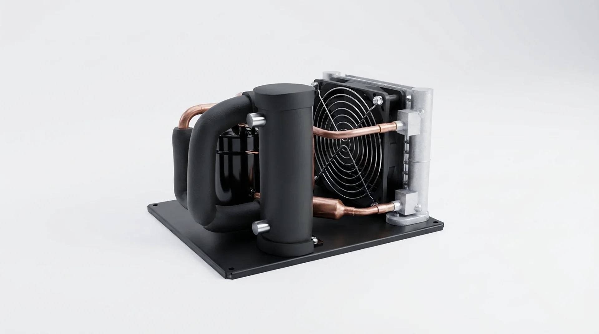
Refrigeration Chiller: The heart of the system removes heat from process coolant through vapor compression refrigeration. Compact DC chillers like RIGID’s DV series provide 450W to 3,000W cooling capacity in footprints small enough for equipment integration. The chiller’s evaporator absorbs heat from circulating coolant, lowering its temperature before returning it to the process. Chiller selection depends on required cooling capacity, ambient temperature range, and available electrical power (12V, 24V, or 48V DC).
Circulation Pump: Moves coolant through the system at sufficient flow rate and pressure to overcome piping resistance and deliver adequate heat transfer at equipment heat exchangers. Centrifugal pumps suit most applications, providing flow rates from 2 to 15 liters per minute depending on system size. Pump sizing requires calculating total system pressure drop including piping, fittings, heat exchangers, and chiller internal resistance. Undersized pumps cause insufficient flow and poor cooling; oversized pumps waste energy and may cause flow noise.
Coolant Reservoir: Provides thermal mass to buffer short-term load variations and accommodates coolant expansion during temperature changes. Reservoir volume typically equals 1.5 to 3 times the system’s total coolant volume, depending on load variability. Insulated reservoirs minimize ambient heat gain. Transparent reservoirs or level indicators enable visual monitoring of coolant level. The reservoir also serves as a deaeration point, allowing dissolved air to separate from coolant before entering the pump.
Heat Exchangers: Transfer thermal energy between process equipment and coolant. Plate heat exchangers offer high efficiency in compact packages, suitable for liquid-to-liquid cooling. Cold plates mount directly to heat-generating components, providing low thermal resistance. Heat exchanger sizing depends on heat load, coolant flow rate, and allowable temperature rise. Undersized heat exchangers cause excessive coolant temperature rise; oversized units add unnecessary cost and pressure drop.
System Sizing: Cooling Load and Flow Rate Calculations
Proper sizing ensures adequate cooling capacity without excessive oversizing that increases cost and reduces efficiency:
Total Heat Load: Sum all heat sources in the system. Equipment heat dissipation comes from manufacturer specifications or measured power consumption. A 1kW laser generates approximately 1kW of waste heat. A 500W power supply at 90% efficiency dissipates 50W. Ambient heat gain through piping and reservoir depends on insulation quality—insulated piping gains 10-20W per meter in 25°C ambient, uninsulated piping gains 50-100W/m. Safety factors of 1.1 to 1.2 account for measurement uncertainties and future load increases.
Required Flow Rate: Calculate from heat load and allowable temperature rise using Q = ṁ × Cp × ΔT, where Q is heat load (W), ṁ is mass flow rate (kg/s), Cp is specific heat capacity (4,186 J/kg·K for water), and ΔT is temperature rise (K). For a 1,000W heat load with 5°C temperature rise: ṁ = 1,000W ÷ (4,186 J/kg·K × 5K) = 0.048 kg/s = 2.9 L/min. Smaller temperature rises require higher flow rates but improve heat transfer efficiency. Typical systems use 3-7°C temperature rise as a compromise between flow rate and heat transfer performance.
Pressure Drop Budget: Calculate total system pressure drop to size the pump. Piping pressure drop depends on flow rate, pipe diameter, length, and number of fittings. Use Darcy-Weisbach equation or online calculators for accurate results. Heat exchanger pressure drop comes from manufacturer data. Chiller internal pressure drop typically ranges from 0.2 to 0.5 bar for compact units. Total system pressure drop typically ranges from 0.5 to 2.0 bar depending on piping layout complexity. Select pump with sufficient head pressure to overcome total system resistance at required flow rate.
Example Calculation: A laser cooling system requires 1,200W cooling capacity. Equipment allows 5°C coolant temperature rise. Required flow rate: 1,200W ÷ (4,186 J/kg·K × 5K) = 0.057 kg/s = 3.4 L/min. Piping layout includes 5 meters of 10mm ID tubing, 6 elbows, 2 quick disconnects, and a plate heat exchanger. Estimated pressure drop: piping 0.3 bar, fittings 0.2 bar, heat exchanger 0.4 bar, chiller 0.3 bar, total 1.2 bar. Select pump rated for 4 L/min at 1.5 bar head pressure (includes safety margin). Select chiller with 1,500W capacity (1.25× safety factor) such as RIGID DV1920E series.
Coolant Selection: Water, Glycol, or Specialty Fluids
Coolant choice affects heat transfer performance, freeze protection, and system compatibility:
Pure Water: Offers highest heat transfer coefficient and lowest viscosity, maximizing cooling efficiency. Suitable for indoor applications where ambient temperature never drops below 5°C. Requires corrosion inhibitors to prevent metal oxidation in mixed-metal systems. Deionized water prevents electrical conductivity issues in systems with exposed electrical components. Pure water provides best performance but lacks freeze protection.
Water-Glycol Mixtures: Ethylene glycol or propylene glycol mixed with water provides freeze protection for outdoor or cold-storage applications. 30% glycol mixture protects to -15°C, 50% mixture protects to -35°C. Glycol reduces heat transfer coefficient by 10-20% and increases viscosity, requiring higher pump power. Propylene glycol offers lower toxicity than ethylene glycol, preferred for food processing or medical applications. Glycol concentration should match the lowest expected ambient temperature with appropriate safety margin.
Specialty Fluids: Dielectric fluids enable direct immersion cooling of electronics without electrical insulation concerns. Fluorinated fluids offer wide temperature ranges and chemical stability but cost significantly more than water-glycol. Mineral oils provide good heat transfer at low cost but require careful material compatibility checks. Specialty fluids suit niche applications where water-glycol cannot meet requirements.
Coolant Properties Impact: Higher viscosity fluids require more pump power and cause higher pressure drop. Lower thermal conductivity reduces heat transfer efficiency, requiring higher flow rates or larger heat exchangers. Coolant selection involves trade-offs between performance, cost, safety, and environmental considerations. For most compact liquid chiller systems operating indoors above 5°C, pure water with corrosion inhibitors offers optimal performance.
Piping Design and Insulation Best Practices
Proper piping minimizes pressure drop, prevents air entrainment, and reduces ambient heat gain:
Pipe Sizing: Larger diameter pipes reduce pressure drop but increase coolant volume and cost. Smaller pipes save space and coolant but increase pumping power. Optimal pipe diameter balances these factors—typical velocities range from 0.5 to 2.0 m/s for liquid cooling systems. For 4 L/min flow rate, 10mm ID tubing provides 0.85 m/s velocity (good balance). 8mm ID tubing gives 1.3 m/s (acceptable but higher pressure drop). 12mm ID tubing gives 0.6 m/s (lower pressure drop but larger volume).
Piping Layout: Minimize total length and number of fittings to reduce pressure drop. Avoid high points where air can accumulate—slope piping upward toward reservoir to enable air purging. Use flexible tubing for vibration isolation between chiller and equipment. Support rigid piping to prevent stress on component connections. Quick-disconnect fittings enable easy maintenance but add pressure drop—use only where disconnection is necessary.
Insulation: Closed-cell foam insulation prevents condensation on cold piping and reduces ambient heat gain. 10mm wall thickness suits most applications. Insulation reduces heat gain by 70-80% compared to bare piping. In high-humidity environments, vapor barriers prevent moisture ingress into insulation. Insulation pays for itself through reduced chiller energy consumption and prevents water damage from condensation dripping.
Air Management: Air trapped in liquid cooling systems causes flow noise, reduces heat transfer, and can lead to pump cavitation. Install automatic air vents at system high points. Fill systems slowly from the lowest point to minimize air entrainment. Operate pump at low speed during initial fill to allow air to escape. Reservoir design should include a deaeration zone where flow velocity is low enough for bubbles to rise and separate.

Control Strategies: Temperature Regulation and System Protection
Effective control maintains setpoint temperature while protecting components from damage:
Temperature Control: PID controllers modulate chiller compressor speed or on-off cycling to maintain coolant temperature within tolerance. Proportional control responds to temperature error magnitude. Integral control eliminates steady-state offset. Derivative control responds to rate of temperature change, improving stability. Well-tuned PID controllers maintain ±0.5°C temperature stability for most applications. Tighter tolerances (±0.2°C) require more sophisticated control and higher-quality sensors.
Flow Monitoring: Flow switches detect loss of coolant circulation, triggering alarms or equipment shutdown to prevent overheating. Paddle-type flow switches suit most applications. Thermal flow sensors provide quantitative flow measurement for advanced diagnostics. Minimum flow rate thresholds should be set above the level where heat transfer becomes inadequate—typically 70-80% of design flow rate.
Pressure Monitoring: High-pressure switches protect chiller compressor from excessive discharge pressure caused by condenser fouling or high ambient temperature. Low-pressure switches detect refrigerant leaks or evaporator icing. Coolant loop pressure sensors detect pump failure or piping leaks. Pressure monitoring prevents catastrophic failures and enables predictive maintenance.
Temperature Limits: High-temperature alarms warn of inadequate cooling capacity or system malfunction before equipment damage occurs. Low-temperature alarms prevent freezing in systems using pure water. Alarm setpoints should provide sufficient warning time for corrective action—typically 5-10°C above normal operating temperature for high-temperature alarms.
Interlocks and Safety: Equipment should not operate without confirmed coolant flow and temperature within acceptable range. Chiller should shut down if coolant temperature cannot be maintained within limits. Pump should stop if chiller fails to prevent coolant overheating. Proper interlocks prevent equipment damage and ensure safe operation.
Integration Considerations for Equipment Manufacturers
OEM integration requires attention to mechanical, electrical, and thermal interfaces:
Mechanical Integration: Compact DC chillers like RIGID’s DV series measure approximately 350×260×180mm for 450-550W models, enabling integration into equipment enclosures or mounting on equipment frames. Vibration isolation mounts prevent chiller vibration from transmitting to sensitive equipment. Mounting orientation affects condenser airflow—ensure adequate clearance for air intake and exhaust. Weight distribution matters for mobile equipment—chillers weigh 5-15kg depending on capacity.
Electrical Integration: DC chillers operate from 12V, 24V, or 48V power supplies, matching common equipment voltages and eliminating AC-DC conversion losses. Current draw ranges from 8-20A depending on capacity and voltage. Inrush current during compressor startup can reach 2-3× running current—power supplies must handle peak loads. Control signals (temperature setpoint, enable/disable, alarm outputs) typically use 0-5V or 0-10V analog signals or digital protocols like Modbus.
Thermal Integration: Heat rejection from air-cooled chillers adds to equipment enclosure thermal load. A 1,000W chiller cooling a 1,000W load rejects approximately 1,200W to ambient air (cooling load plus compressor power). Enclosure ventilation must handle this heat rejection to prevent ambient temperature rise. Water-cooled chillers eliminate heat rejection into equipment enclosure but require facility water supply.
Serviceability: Design systems for easy coolant filling, air purging, and filter replacement. Provide access to pump and chiller for maintenance without disassembling entire equipment. Include drain ports at system low points for complete coolant removal during service. Transparent tubing or sight glasses enable visual inspection of coolant condition and flow.
Common Design Mistakes and How to Avoid Them
Learning from typical errors saves time and prevents performance issues:
Undersized Chiller: Selecting chiller capacity equal to heat load without safety margin causes inadequate cooling during high ambient temperature or peak load conditions. Always apply 1.15-1.25× safety factor to calculated heat load. Account for ambient heat gain through piping and reservoir. Consider future load increases if equipment may be upgraded.
Inadequate Flow Rate: Insufficient coolant flow causes excessive temperature rise and poor heat transfer at equipment heat exchangers. Calculate required flow rate from heat load and allowable temperature rise. Verify pump can deliver required flow rate against total system pressure drop. Don’t assume manufacturer’s rated flow applies to your system—pressure drop reduces actual flow.
Poor Air Management: Trapped air causes flow noise, reduces heat transfer, and can damage pumps. Design piping to slope upward toward reservoir. Install air vents at high points. Fill systems slowly from bottom. Operate at low flow during initial fill to allow air escape. Reservoir should include deaeration zone.
Insufficient Insulation: Uninsulated cold piping causes condensation dripping and adds significant heat load. Insulate all piping operating below ambient temperature. Use closed-cell foam with vapor barrier in humid environments. Insulation pays for itself through reduced chiller energy consumption and prevents water damage.
Ignoring Pressure Drop: Selecting pump based only on flow rate without considering system pressure drop results in insufficient flow. Calculate total pressure drop including piping, fittings, heat exchangers, and chiller. Select pump with adequate head pressure at required flow rate. Include safety margin for filter fouling and coolant viscosity changes.
For detailed specifications on compact DC liquid chillers suitable for system integration, explore RIGID’s DV series liquid cooling solutions offering 450W to 3,000W capacity in space-saving designs optimized for equipment-level cooling applications.