
Melting Point Apparatus Cooling Starts With a Stable Cold Sink, Not a Ramp
A capillary melting point apparatus is built to heat. Its furnace, its control loop and its published specifications all assume the sample starts at room temperature and goes up. The moment you need a melting point below ambient — a fat, a wax, a cryoprotectant, a low-melting active pharmaceutical ingredient, a polymorph that transitions at −12 °C — that assumption breaks, and melting point apparatus cooling becomes an external problem you have to solve yourself.
The instinct is to look for a chiller that can follow the measurement ramp downward. That is the wrong architecture and it produces disappointing results. In a working sub-ambient setup the chiller does not ramp at all. It holds a fixed cold sink well below the lowest transition of interest, and the instrument’s own heater does the ramping against it. Understanding that division of labor is what makes the selection straightforward.
This guide works through setpoint selection, the surprisingly small capacity requirement, and the two problems that actually cause sub-ambient melting point work to fail: frost on the optical path, and coolant behavior below 0 °C.
Why Sub-Ambient Melting Points Need an External Cold Sink
Melting point apparatus cooling exists to satisfy one requirement. A melting point determination is a controlled ramp through the transition, typically at 1 °C/min or slower near the expected point, with the operator or a detector watching the sample change state. Two conditions must hold:
- The sample must start comfortably below the transition, fully solidified and thermally equilibrated.
- The ramp through the transition must be slow, monotonic and repeatable.
For a substance melting at +60 °C, room air satisfies the first condition for free. For one melting at −10 °C, nothing in the room is cold enough, and the block has to be driven down by an external source before the measurement can even begin. That external source is a recirculating chiller connected to a jacketed or plated stage.
The same requirement appears in adjacent work: freezing point determination, congealing point of waxes and fats, cloud point, and crystallization onset studies. All of them share the pattern of pre-cool, equilibrate, then ramp.
The Chiller Does Not Ramp — the Instrument Does
This is the single most useful thing to understand before selecting equipment.
A recirculating chiller’s control loop regulates its own reservoir. Its response time is measured in minutes, dominated by the thermal mass of the coolant and the reservoir. A melting point ramp needs resolution measured in tenths of a degree per minute at the sample. Asking the chiller to produce that ramp means asking a slow, coarse loop to do a fast, fine job, and the result is overshoot, hunting, and a ramp that is neither monotonic nor repeatable.
The architecture that works puts them in series rather than asking one to do both:
| Element | Job | Set to |
|---|---|---|
| Recirculating chiller | Hold a constant cold sink | A fixed value below the lowest transition of interest |
| Instrument heater | Produce the measurement ramp | Controlled by the instrument, working against the sink |
| Stage / block | Sum the two and present one temperature to the sample | Measured by the instrument’s own sensor |
Once framed this way, the chiller specification collapses to two numbers: how cold it must hold, and how stable that hold must be. Ramp rate, overshoot and settling time become the instrument’s problem, not the chiller’s.
Setpoint Selection: How Far Below the Transition
Setpoint selection is the first real decision in melting point apparatus cooling. The sink has to sit below the lowest transition you intend to measure, with enough margin for the heater to have authority across the whole ramp. Three terms set that margin:
- Equilibration headroom — The sample must reach a stable starting temperature clearly below the transition, not just touch it. A few degrees is the practical minimum.
- Heater authority — The instrument’s heater must be able to overcome the sink and drive the block up at the required rate. Too cold a sink and the ramp becomes slow or the heater saturates; too warm and the low end is unreachable.
- Loop losses. The stage never reaches the chiller’s setpoint exactly. Ambient gain along the hoses and the temperature rise across the stage both sit between the reservoir and the sample.
A workable starting rule is to set the sink roughly 10–15 K below the lowest transition of interest, then verify against a known reference material and adjust. Treat that as a starting estimate rather than a specification — the correct value depends on your stage design and heater sizing, and it is quickly found empirically.
Worked Example: A Stage Working Down to −25 °C
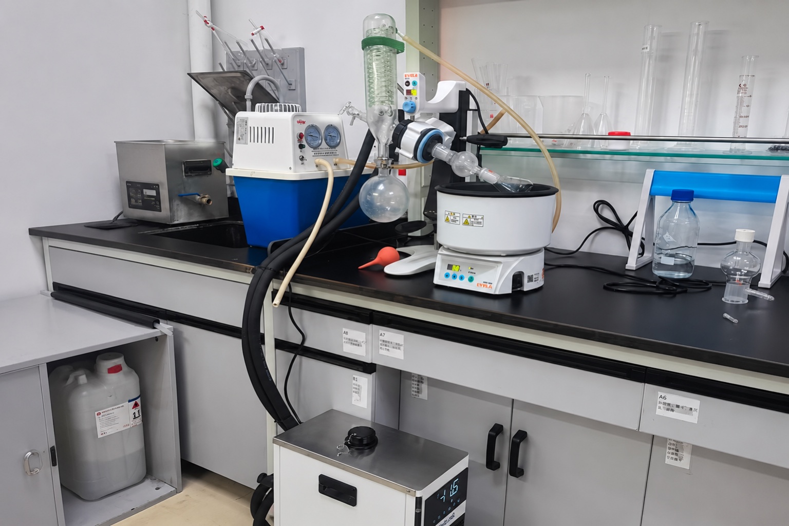 Numbers make the capacity question concrete. Consider a jacketed melting point block being held at a −25 °C sink in a 22 °C laboratory, connected by 1.5 m of insulated hose each way.
| Input | Value used | Basis |
|---|---|---|
| Sink setpoint | −25 °C | Assumed; ~12 K below a −13 °C lowest transition |
| Room ambient | 22 °C | Assumed |
| Block and jacket mass | 1.2 kg aluminum | Assumed for a benchtop block |
| Aluminum specific heat | 0.90 kJ/kg·K | Reference property near 20 °C |
| Steady heat leak into block | 25 W allowance | Assumed; insulated block, 47 K difference |
| Insulated hose gain | 35 W allowance | Assumed for 3 m total at 47 K difference |
| Pump heat | 30 W allowance | Assumed; pump power not published |
| Heater power during ramp | 60 W | Assumed; the heater’s output also lands on the sink |
Steady-state load while holding the sink:
25 W (block leak) + 35 W (hose) + 30 W (pump) = 90 W
Load while the instrument is ramping, since the heater’s output ultimately has to be removed as well:
90 W + 60 W (heater) = 150 W at −25 °C
Pull-down energy for the block itself, one time at start of session:
1.2 kg × 0.90 kJ/kg·K × 47 K = 51 kJ, which at 150 W of available surplus is under ten minutes of block cool-down — the coolant volume and hoses take longer than the block does.
The result is worth pausing on. A demanding sub-ambient melting point setup asks for roughly 150 W at −25 °C. That is a fraction of what the smallest machine in a sub-zero laboratory chiller range delivers.
Capacity Is Not the Constraint — Stability Is
This is where melting point apparatus cooling differs from most chiller sizing. When the load is 150 W and the smallest available machine is rated at 450 W, the selection question inverts. You are no longer asking whether the chiller is big enough. You are asking whether it behaves well when lightly loaded.
Three consequences follow, and they are the opposite of the usual sizing advice:
- Turndown matters more than capacity. A machine that cannot modulate below its load will cycle, and every cycle puts a temperature ripple into the sink that shows up as noise in the measurement. Variable-speed operation is what keeps a light load quiet.
- Extra capacity buys faster pull-down at the start of a session and nothing else. It does not improve the measurement.
- Stability specifications become the deciding number. For the MiniCool range the published figure is ±0.1 °C, though the test point and load condition are not stated on the product pages — so treat it as an indication of control quality and confirm the value at your own sink temperature and load.
This also means there is little reason to reach past the smallest model in the range for this application. The capacity headroom is already large.
Frost and Condensation on the Optical Path
The problem that actually ruins melting point apparatus cooling installations is not thermal. It is water.
A block held at −25 °C in a 22 °C room sits far below the dew point of the surrounding air. Moisture condenses and then freezes on every cold surface it can reach, including the viewing window, the capillary tubes, and the outside of the hoses. Frost on the optical path makes the transition impossible to observe; frost inside a capillary changes what you are measuring.
The countermeasures are established practice and worth designing in from the start:
- A dry gas purge over the sample area — dry nitrogen or dry compressed air — to keep humid room air off the cold surfaces.
- Continuous insulation on every cold surface outside the measurement zone, with no gaps at fittings. Bare fittings are where dripping starts.
- A drip path and a way to catch meltwater when the system warms back up, so it does not run into the instrument or across the bench.
- Sealing the enclosure around the stage so the cold volume is small and the purge is effective.
None of this is chiller selection, but all of it determines whether the installation works. Frost management is the difference between a setup that produces clean data and one that gets abandoned after a month.
Coolant and Loop Selection Below 0 °C
Coolant choice is the last piece of melting point apparatus cooling. Water is not usable at these temperatures. A glycol solution or a silicone-based heat transfer fluid is required, chosen so its freezing point sits comfortably below the sink setpoint — not merely at it, since local temperature at the evaporator surface is lower than the bulk reservoir.
Two properties change the loop design:
- Viscosity rises steeply as temperature falls. A fluid that pumps easily at 20 °C can more than double its viscosity by −25 °C, raising pressure drop and reducing flow for the same pump. A small stage with narrow internal passages is exactly where this bites.
- Specific heat is lower than water’s, so a given heat load produces a larger temperature rise across the stage at the same flow rate.
Because MiniCool’s pump flow and head figures are not published, a stage with restrictive internal passages is a case where the flow figure should be requested rather than assumed. Fluid selection and mixing ratios are covered in more depth in our guide to glycol and water coolant ratios.
Matching to the MiniCool Range
With a light load and a sub-zero sink, the selection is straightforward.
| Model | Published capacity | Temperature range | Stability | Dimensions | Noise |
|---|---|---|---|---|---|
| MiniCool 450 | 450 W | 0 °C to −40 °C | ±0.1 °C (test point not stated) | 200 × 430 × 450 mm | <45 dB |
| MiniCool 800 | 800 W | 0 °C to −40 °C | ±0.1 °C (test point not stated) | 200 × 430 × 450 mm | <45 dB |
| MiniCool 850 | 850 W | 0 °C to −40 °C | ±0.1 °C (test point not stated) | 200 × 430 × 450 mm | <45 dB |
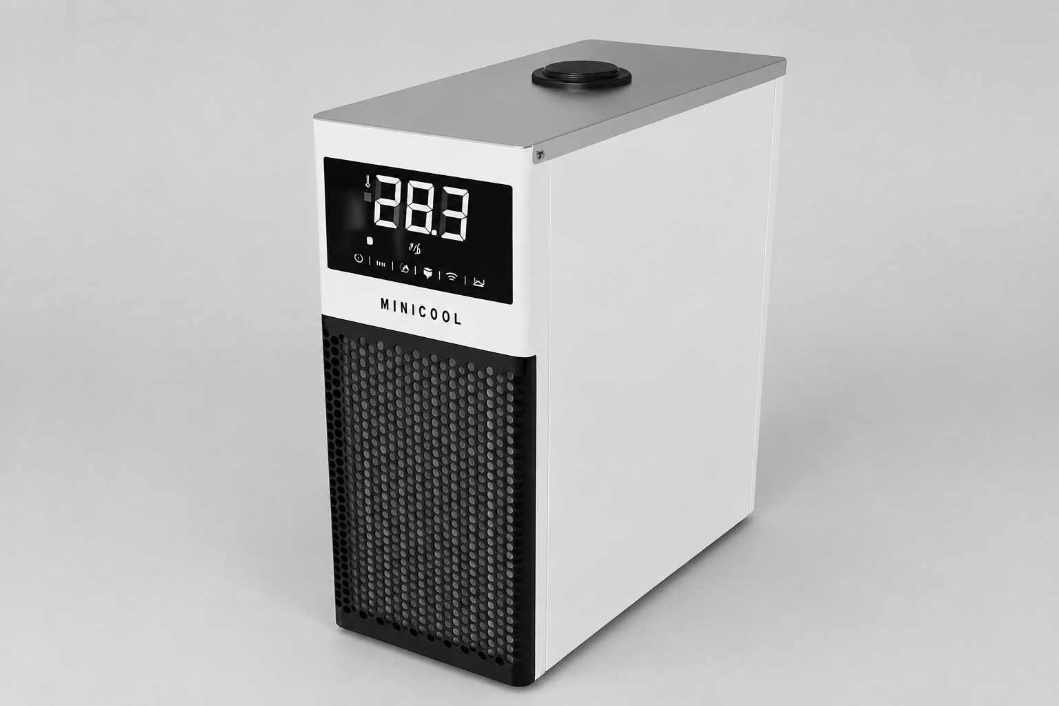 For a 150 W load the 450 W model looks comfortable on paper, but the published capacities carry no stated test condition, so the figure that matters is the capacity available at your sink temperature — confirm it for −25 °C rather than reading the headline number as available across the range. Since all three models share the same 200 × 430 × 450 mm enclosure, moving up the range costs bench space only in the sense of not saving any. The published range of 0 °C to −40 °C covers the sub-ambient transitions this application targets. Full model data is on the MiniCool product page, and the <45 dB figure matters more than usual here because the instrument sits at a bench where someone is watching a capillary for several minutes at a time.
One boundary to respect: MiniCool is specified for setpoints from 0 °C down to −40 °C. If your instrument work also requires a positive-temperature sink — a thermostatted stage above ambient, for instance — that falls outside the published standard range and should be confirmed with RIGID rather than assumed. The DV compact liquid chiller covers 100–550 W across a published −20 °C to +20 °C range and is the catalog answer for positive-temperature stages.
Where Selection Goes Wrong
Expecting the chiller to produce the ramp
Programming a temperature ramp into the chiller instead of letting the instrument’s heater do it. The chiller’s loop is too slow and too coarse, and the resulting ramp is neither monotonic nor repeatable.
Sizing on capacity when the load is tiny
Choosing a larger model because the application sounds demanding. At 150 W the constraint is turndown and stability, not watts. Extra capacity only shortens pull-down.
Ignoring frost until after installation
Treating the purge and insulation as accessories. On a −25 °C stage in a normal laboratory they are load-bearing parts of the design.
Choosing coolant by freezing point alone
A fluid that does not freeze at −25 °C may still be too viscous to circulate properly through a small stage. Check viscosity at the setpoint, not just the freeze point.
Setting the sink too cold
Over-cooling the sink to “have margin” leaves the heater fighting a larger gradient, which slows the ramp and can make the low end of the heater’s authority the limiting factor.
The Selection Sequence
- List the lowest transition temperature you need to measure.
- Set the sink target roughly 10–15 K below it as a starting point.
- Estimate the steady load: block heat leak, hose gain, pump heat, plus the heater output during ramps.
- Confirm the candidate chiller’s capacity at that sink temperature. Published capacities for this range carry no stated test condition, so the headline number cannot be assumed available at −25 °C.
- Check turndown and stability, because at these loads they decide the measurement quality.
- Select a coolant on viscosity at setpoint as well as freeze point.
- Design frost management — purge, insulation, drip path — before installation, not after.
- Validate against a reference material and adjust the sink empirically.
Comparable sub-zero laboratory applications and their setpoint ranges are collected in our overview of −40 °C circulator applications.
If you would rather have the operating point confirmed than estimated, send the following and our engineers will return a model recommendation with the capacity at your condition: lowest transition temperature, target sink setpoint, stage or block mass and material, heater power, hose length and internal diameter, coolant fluid, maximum room ambient, and whether the installation is a single bench instrument or a multi-station setup. Send your operating conditions to our engineering team.
Frequently Asked Questions
How cold does the chiller need to be for a melting point apparatus?
Melting point apparatus cooling is specified by sink temperature: set it below the lowest transition you intend to measure, with enough margin for the instrument’s heater to control the ramp. Roughly 10–15 K below the lowest transition is a reasonable starting point, then verify with a reference material. For most sub-ambient organic work this puts the sink somewhere between −10 °C and −30 °C, which sits inside the published 0 °C to −40 °C range of a sub-zero laboratory chiller.
Can the chiller do the temperature ramp instead of the instrument?
In practice, no. A recirculating chiller regulates its own reservoir, and the thermal mass of the coolant makes its response slow and coarse relative to the tenths-of-a-degree-per-minute resolution a melting point determination needs. Let the chiller hold a fixed sink and let the instrument’s heater produce the ramp against it.
Why is my sample frosting over before it melts?
The cold surfaces are below the dew point of the room air and moisture is condensing and freezing on them. The fix is a dry gas purge over the sample area plus continuous insulation on every cold surface outside the measurement zone, with particular attention to fittings, which are the usual gap. This is a design requirement on any sub-ambient stage, not an occasional nuisance.
Do I need a bigger chiller for faster pull-down?
Only if session start-up time is a real constraint. In the worked example above, the block itself cools in under ten minutes and the coolant volume and hoses dominate the wait. Extra capacity shortens that one-time wait but does nothing for measurement quality, which is set by stability and turndown.
What coolant should I use for a sub-zero melting point stage?
A glycol solution or silicone-based heat transfer fluid with a freezing point comfortably below your sink setpoint. Check viscosity at the setpoint as well: viscosity rises steeply as temperature falls, and a small stage with narrow internal passages can lose significant flow at −25 °C even with a fluid that is nowhere near freezing.
Can the same chiller serve a positive-temperature stage?
MiniCool is specified for 0 °C down to −40 °C, so a positive-temperature sink falls outside its published standard range and should be confirmed with RIGID rather than assumed. For a stage that needs to be held between 0 °C and +20 °C, the DV compact liquid chiller range is the catalog answer.