
Angle Lock: The decision moment is choosing between passive cooling, thermoelectric modules, and active vapor-compression for a sealed medical device enclosure. Two primary failure modes are thermal drift causing inaccurate diagnostic results and contaminant ingress from improper open-loop cooling. The dominant constraint is maintaining stable internal temperatures in a compact, sealed, and often noise-sensitive environment.
Choosing a Micro DC Air Conditioner for Medical Equipment Cabinet Cooling
A next-generation diagnostic analyzer fails its final validation run. The cause is not a flaw in the chemistry or the software, but thermal drift in the optical sensor array after 45 minutes of continuous operation. The heat generated by the onboard FPGA and power supply has saturated the compact, sealed enclosure, skewing critical measurements. This scenario is a familiar and costly setback for OEM engineers in the medical and laboratory equipment space. The stakes are immense: delayed product launches, compromised diagnostic accuracy, and the risk of premature component failure in the field.
Simple fans are not an option for sealed enclosures, and thermoelectric coolers often struggle with efficiency under significant heat loads. This is the critical juncture where engineers must evaluate more robust thermal management solutions. By the end of this article, you will be able to identify the specific performance thresholds and environmental constraints that make an active, vapor-compression system the commonly required engineering choice. In this analysis, we prioritize long-term thermal stability and enclosure integrity over minimal upfront cost, exploring why a micro dc air conditioner for medical equipment cabinet designs is often the most reliable path for high-value, sensitive systems.
Deployment Context: Two Real-World Scenarios
The need for advanced enclosure cooling is not theoretical. It arises from specific design constraints and environmental challenges that push passive or legacy cooling methods past their breaking point.
Scenario A: Automated Sample Analyzer
An OEM developing a new automated immunoassay system packaged microfluidics, precision optics, and control electronics into a compact tabletop chassis. During endurance testing, engineers discovered that heat soak from the control board and stepper motors caused the internal temperature to climb 15°C above ambient, leading to unacceptable drift in sensor readings. The primary constraint was the sealed enclosure, a design requirement to protect sensitive reagents and samples from airborne contaminants and to manage potential bio-fluid spills. This rendered traditional fan-and-filter cooling completely unsuitable.
Scenario B: Point-of-Care Diagnostic Cart
A company designed a mobile diagnostic cart for use in busy hospital wards. The cart integrated an embedded computer, a high-current power supply, and a specialized imaging module. In early field trials, the units experienced intermittent shutdowns, traced back to the CPU throttling and eventually overheating. The cart’s fan-based cooling system, located near the floor, was ingesting dust and textile fibers, clogging the heat sinks. The key constraint was maintaining reliable performance in a non-controlled clinical environment while protecting the internal electronics from dust and the occasional spilled liquid, necessitating a move to sealed enclosure cooling for medical devices.
Common Failure Modes and Design Constraints
When thermal management is insufficient, the symptoms can range from subtle performance degradation to catastrophic failure. For medical and lab equipment, the consequences are particularly severe. Here are the most common failure modes, ranked by impact:
- Symptom: Thermal Drift → Cause: Component Overheating → Why it matters: Leads to inaccurate diagnostic results, failed calibrations, and non-compliance with medical standards.
- Symptom: Intermittent Shutdowns → Cause: CPU/FPGA Throttling → Why it matters: Causes unreliable operation during critical procedures, potential data loss, and unacceptable system downtime.
- Symptom: Reduced Component Lifespan → Cause: Sustained High Temperatures → Why it matters: Results in premature failure of expensive electronics, leading to increased warranty claims and damage to brand reputation.
- Symptom: Contaminant Ingress → Cause: Open-Loop (Fan) Cooling → Why it matters: Allows dust, moisture, or aerosols to foul sensitive optics, short-circuit PCBs, and compromise sterile processes.
- Symptom: Excessive Noise → Cause: High-RPM Fans or Inefficient Coolers → Why it matters: Fails to meet noise level requirements for patient-facing or laboratory environments and causes operator distraction.
- Symptom: Condensation Buildup → Cause: Internal Air Cooled Below Dew Point → Why it matters: Can cause electrical shorts on high-density circuit boards and long-term corrosion.
- Symptom: High Power Consumption → Cause: Inefficient Cooling Technology (e.g., TEC at high delta-T) → Why it matters: Drains batteries on mobile carts faster and increases the total cost of ownership for line-powered equipment.
Engineering Fundamentals: Closed-Loop Cooling
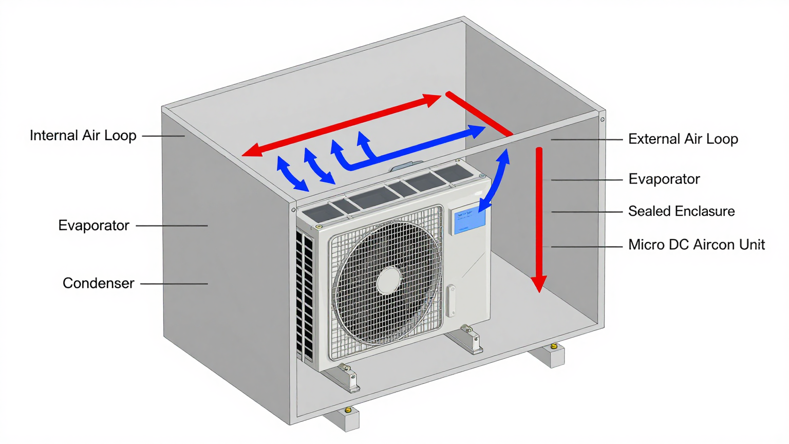
To overcome these failure modes, particularly in sealed enclosures, engineers must shift from open-loop to closed-loop cooling. A micro dc air conditioner for medical equipment cabinet is a prime example of a closed-loop system. The core principle is air circuit separation.
The unit creates two completely independent air paths:
- The Internal Loop: A fan draws warm air from inside the sealed cabinet, passes it over a cold evaporator coil where heat is absorbed, and then circulates the cooled, dehumidified air back into the cabinet. This continuously removes heat from the electronics without introducing any outside air.
- The External Loop: A second fan draws ambient air from outside the cabinet and passes it over a hot condenser coil. The heat captured from the internal loop is transferred to this ambient air and expelled into the surrounding environment.
This separation is fundamental to maintaining the integrity of a sealed enclosure. It allows for active heat removal while protecting sensitive internal components from dust, moisture, and other external contaminants. This is how a system can be cooled effectively while upholding a specific Ingress Protection (IP) rating.
Misconception vs. Engineering Reality
A common misconception among teams transitioning from consumer to industrial-grade electronics is that a simple fan or a basic heat sink is sufficient for thermal management. This assumption often fails in the context of medical devices.
- Misconception: “We can just add a fan to cool the cabinet.”
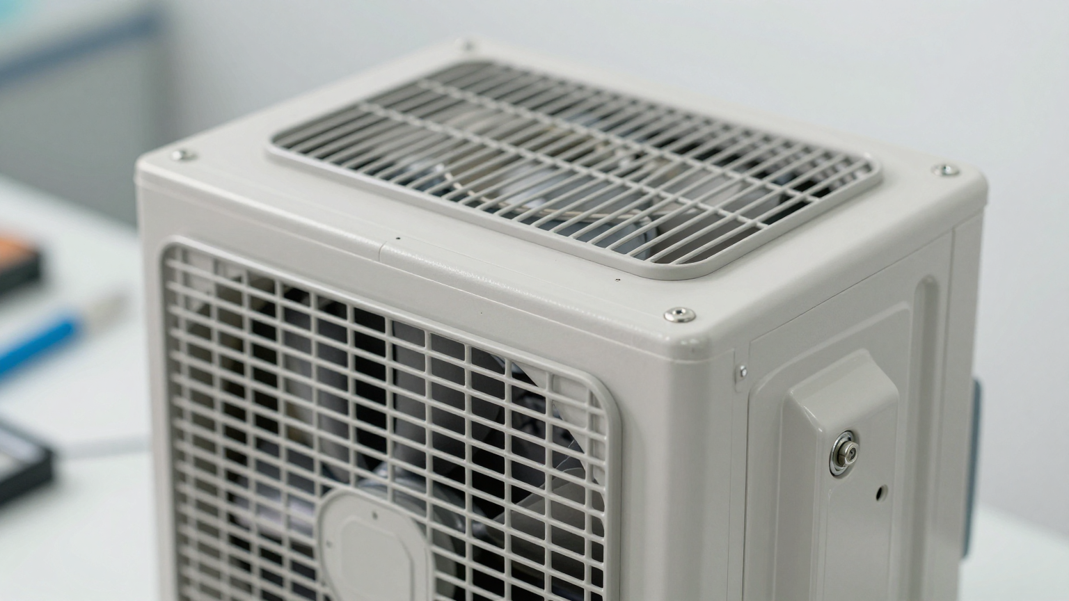
- Correction: A fan only works if two conditions are met: the ambient air is significantly cooler than the target internal temperature, and the enclosure can be open to that ambient air. In a sealed medical cabinet, a fan merely circulates and redistributes hot air, eventually leading to heat saturation. For any application requiring a stable internal temperature—especially one at or below the surrounding ambient temperature—active heat removal via a closed-loop system is a common requirement. The Micro DC Aircon series provides this active, closed-loop functionality.
Key Specifications for Selection
Once the need for active, closed-loop cooling is established, the selection process becomes data-driven. The following specifications are critical go/no-go gates in the design process. The table below shows example parameters for our Micro DC Aircon Pro series, which are often considered for demanding applications requiring a quiet micro dc cabinet air conditioner.
| Model (Example) | Voltage (VDC) | Nominal Cooling Capacity (W) | Refrigerant |
|---|---|---|---|
| DV1910E-AC (Pro) | 12V | 450W | R134a |
| DV1920E-AC (Pro) | 24V | 450W | R134a |
| DV1930E-AC (Pro) | 48V | 450W | R134a |
| DV3220E-AC (Pro) | 24V | 550W | R134a |
When reading these specs for your decision, focus on two primary factors. First, the DC Voltage must align with your equipment’s power bus architecture; 24V and 48V are common in medical and industrial systems. Second, the Nominal Cooling Capacity must exceed your calculated internal heat load. A robust engineering practice is to sum the Thermal Design Power (TDP) of all internal components (processors, power supplies, lasers, etc.) and add a safety margin of at least 20-25% to account for peak loads and high ambient conditions.
Engineering Selection Matrix: Logic Gates for Integration
Choosing the right thermal management technology involves passing through a series of engineering logic gates. For high-value medical equipment, these gates are often unforgiving. A wrong turn can lead to a full product redesign.
Gate 1: The Sealed Enclosure Mandate
- Constraint Gate: Environmental Protection vs. Airflow. The system requires protection from dust, moisture, or bio-contaminants.
- Decision Trigger: If the enclosure must meet a specific IP rating (e.g., IP54 or higher) to ensure reliability and safety.
- Engineering Resolution: This immediately makes open-loop cooling with fans and filters a non-viable path. The choice narrows to two primary options: a thermoelectric cooler (TEC) or a vapor-compression micro dc air conditioner for medical equipment cabinet.
- Integration Trade-off: This decision increases upfront system cost and mechanical complexity but is a typically required requirement for maintaining a clean internal environment and achieving high reliability in real-world medical settings.
Gate 2: The Below-Ambient Cooling Requirement
- Constraint Gate: Internal Target Temperature vs. Maximum Ambient Temperature.
- Decision Trigger: If the internal electronics must be maintained at a temperature (e.g., 28°C) that is below the maximum expected ambient operating temperature (e.g., 35°C in a clinic).
- Engineering Resolution: Passive solutions like heat sinks and even fan-assisted heat exchangers are physically incapable of cooling below ambient. Active refrigeration is required. This confirms the need for either a TEC or a vapor-compression system.
- Integration Trade-off: A dedicated power budget must be allocated to the cooling subsystem. The power draw becomes a key design constraint, especially for battery-powered mobile carts.
Gate 3: Heat Load vs. Coefficient of Performance (COP)
- Constraint Gate: Thermal Load Density vs. System Efficiency.
- Decision Trigger: When the total internal heat load exceeds approximately 200 watts. While TECs are effective for lower heat loads, their efficiency (COP) drops dramatically as the heat load and the temperature differential (delta-T) increase. They generate significant waste heat of their own, adding to the thermal management challenge.
- Engineering Resolution: This is the critical crossover point where a miniature vapor-compression system becomes the superior choice. The COP of a micro dc aircon compact enclosure cooling system is significantly higher than a TEC, especially at higher delta-T. It removes more heat per watt of input power, making it a far more efficient and effective solution for managing substantial heat loads.
- Integration Trade-off: A micro DC aircon typically has a larger volumetric footprint and higher initial cost than a TEC. However, for heat loads above 200W, it results in lower overall power consumption and provides more stable thermal performance, justifying the initial investment.
Implementation and Verification Checklist
Proper integration is as critical as selecting the right unit. A poorly installed cooler will fail to perform, regardless of its specifications. Follow this checklist for a successful deployment.
- Mechanical Integration
- Mounting: Securely fasten the unit to the enclosure wall using the specified cutout dimensions and mounting points. Ensure the structure can support the unit’s weight without vibration.
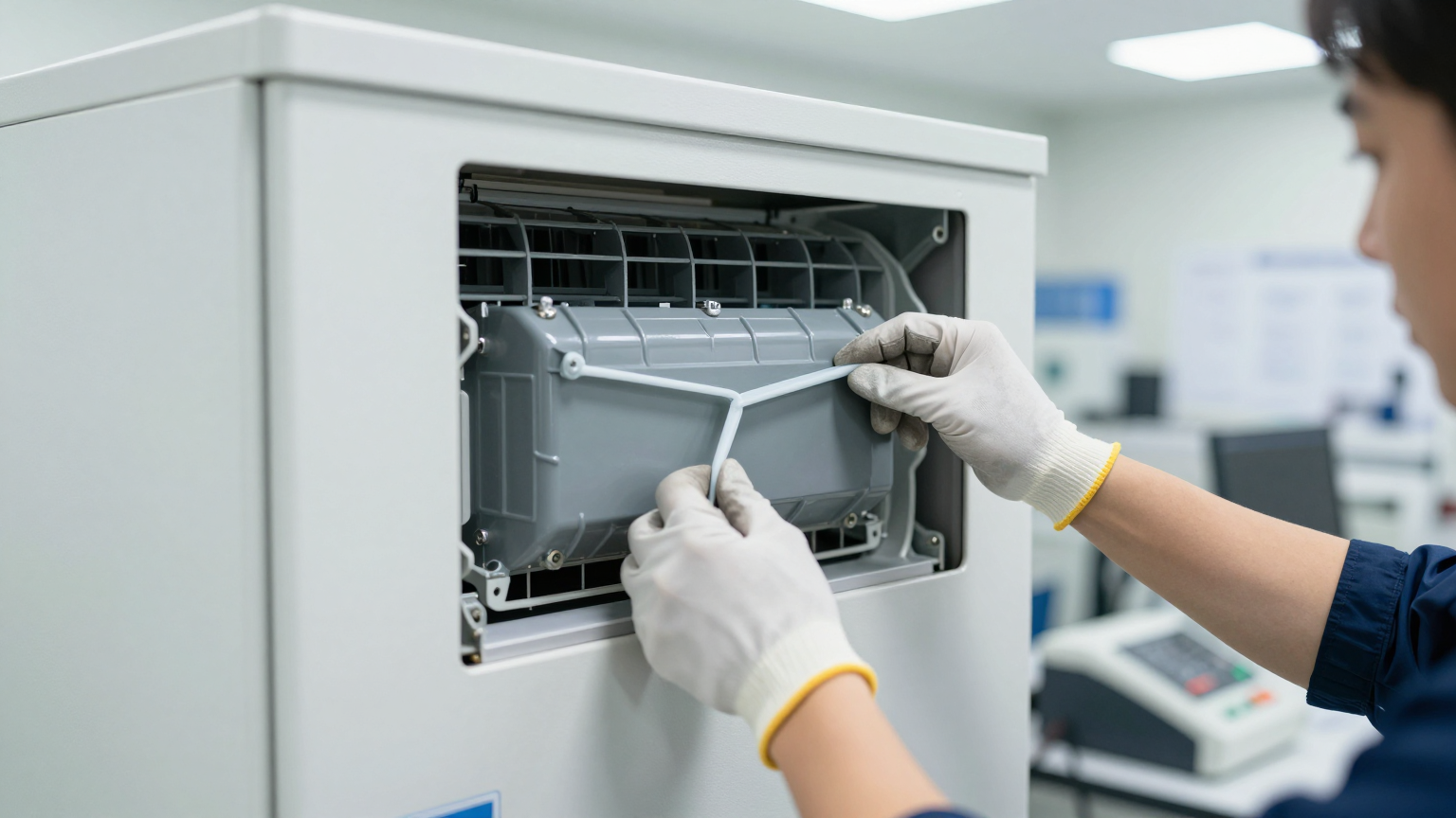
- Sealing: Carefully install the supplied gasket between the unit and the cabinet wall. Verify a continuous, compressed seal around the entire perimeter to maintain the enclosure’s IP rating.
- Airflow Integrity: Check for and remove any obstructions to the internal and external air inlets and outlets. Route cable harnesses and other components to ensure clear pathways for air circulation.
- Electrical Integration
- Power Supply: Connect the unit to a stable DC power bus that matches its voltage rating (12V, 24V, or 48V). The power supply must be rated to handle the cooler’s maximum current draw during startup.
- Circuit Protection: Install an appropriately rated fuse or circuit breaker in line with the power supply to protect the unit and the system.
- Control Wiring: If using variable speed control or remote monitoring features, ensure control signals are properly wired according to the product manual.
- Thermal Validation
- Sensor Placement: Position thermocouples near the most critical heat-generating components (e.g., CPU, FPGA) and at the air return inlet of the cooling unit.
- Acceptance Testing: Place the entire system in a thermal chamber set to the maximum specified ambient operating temperature. Run the equipment under full processing load and log the internal temperatures to confirm they remain within safe, stable limits.
- Maintenance Planning
- External Heat Sink: Ensure the external condenser coils are accessible for periodic inspection and cleaning. In dusty environments, a quarterly check is advisable to prevent airflow blockage.
- Seal and Fan Check: Schedule an annual inspection to verify the integrity of the mounting gasket and the operation of both internal and external fans.
Frequently Asked Questions (FAQ)
1. Should I use a thermoelectric cooler or a micro DC air conditioner for my medical equipment cabinet?
It depends heavily on your heat load. For loads under 150-200W with a small temperature difference between inside and outside, a TEC can be a simpler solution. For heat loads above 200W or when you need to maintain an internal temperature significantly below ambient, a micro dc air conditioner for medical equipment cabinet is far more energy-efficient and powerful.
2. How do I maintain a sealed, IP-rated enclosure while actively cooling it?
This is precisely the problem solved by closed-loop coolers. A micro DC aircon mounts through the cabinet wall with a robust gasket. This design keeps the internal and external air circuits completely separate, allowing heat to be removed without compromising the enclosure’s IP rating against dust or fluids.
3. Will a micro DC air conditioner create condensation inside my cabinet?
Condensation can occur if the internal air is cooled below its dew point. This risk is managed by setting the thermostat appropriately, ensuring the cabinet is well-sealed to prevent humid ambient air from entering, and proper system sizing. Many units also incorporate features for condensate management.
4. What if my equipment is used in a dusty clinic or exposed to direct sunlight?
A sealed enclosure with a micro dc air conditioner for medical equipment cabinet is the ideal solution for dusty environments, as it prevents any contaminants from reaching the electronics. If the cabinet is exposed to direct sunlight, you must account for the additional solar heat load in your total thermal calculation to size the cooler correctly.
5. What is the first thing I must measure before selecting a cooling unit?
Your total internal heat load. You must perform a heat load calculation by summing the power consumption or TDP of every component inside the enclosure (e.g., processors, power supplies, motors, drivers). Always add a a conservative margin to this sum to ensure reliable performance under all conditions.
6. How can I validate the cooling performance after installation?
The most reliable method is empirical testing. Instrument the cabinet with multiple temperature sensors at critical locations. Then, operate the entire system at its maximum processing load within an environmental chamber set to the highest specified ambient temperature. Log the data to confirm that internal temperatures remain stable and within component specifications.
7. Are these units quiet enough for a lab or patient room?
Noise is a critical design consideration. A quiet micro dc cabinet air conditioner that uses a variable-speed BLDC compressor and quality fans is designed for low-noise operation. The noise level depends on the model and the cooling demand, but they are generally suitable for noise-sensitive medical and laboratory environments, often outperforming loud, high-speed fan solutions.
Conclusion: The Right Tool for a Demanding Job
The decision to integrate a micro dc air conditioner for medical equipment cabinet designs is driven by non-negotiable engineering requirements. This technology is the best-fit solution when the application involves a combination of high internal heat loads (typically >200W), a strict need for a sealed enclosure to protect against contaminants, and the requirement to maintain internal temperatures at or below the ambient environment. Its high efficiency and robust performance provide the thermal stability that sensitive, high-value medical and lab instruments demand.
For applications with very low heat loads and minimal temperature differentials, simpler technologies may suffice. However, as medical devices become more powerful and compact, the thermal challenges intensify, making advanced, active cooling an increasingly standard part of the design process. The integration of any thermal management system is unique. For detailed sizing calculations, customization options for mounting, or to discuss solutions for challenging power constraints and harsh environments, we invite you to contact our engineering team.