
Angle: The critical decision is choosing between passive/simple cooling and an active, closed-loop system for a sealed electronics enclosure. The primary failure modes are heat-induced performance throttling and condensation-driven short circuits. The dominant constraint is maintaining the enclosure’s NEMA/IP seal against environmental contaminants.
A Practical Micro DC Air Conditioner Selection Guide for Sealed Enclosures
An industrial control cabinet on a factory floor silently fails. There was no power surge, no catastrophic component failure—just a slow, creeping thermal degradation. The cause? The enclosure’s cooling system, a simple filtered fan, couldn’t handle the combined internal heat load and the sweltering summer ambient temperature. Worse, it pulled in fine, corrosive dust that settled on the electronics. The stakes of such a failure are significant: unplanned downtime, costly field service calls, and damage to your brand’s reputation for reliability. This scenario is a common consequence of miscalculating the thermal management needs of a sealed system.
Choosing the right cooling solution is not just about specifying a component; it’s about designing for system-level integrity. By the end of this guide, you will have a robust engineering framework to determine precisely when an active thermal solution is non-negotiable and how to specify it correctly for long-term performance. In this article, we prioritize maintaining the enclosure’s environmental seal and managing latent heat (humidity) over simply chasing raw cooling power, as this is the most common and critical point of failure in demanding real-world deployments.
Deployment Context: Two Common Scenarios
Theoretical knowledge has its limits. Let’s ground our discussion in two distinct, real-world scenarios where thermal management choices directly impacted operational success.
Scenario A: Outdoor Telecom Cabinet
A sealed cabinet housing 5G signal processing equipment is mounted on a cell tower in a desert region. The original design incorporated a high-efficiency heat exchanger, assuming it would be sufficient. However, during peak summer days with intense solar load, the ambient temperature reached 45°C (113°F). The heat exchanger, unable to cool below ambient, allowed the internal temperature to climb past 60°C, exceeding the operating limits of the sensitive radio electronics. This resulted in performance throttling and intermittent service disruptions, a critical failure for a telecommunications provider.
Scenario B: Food & Beverage Processing Line
A stainless-steel NEMA 4X enclosure on a bottling line contains the PLC and VFDs controlling a conveyor system. The environment is subject to daily high-pressure, high-temperature washdowns for sanitation. Initially, a simple filtered fan was specified to save costs. Within months, moisture ingress from the washdowns bypassed the filter, causing corrosion on the PLC’s I/O terminals and leading to a complete line stoppage. The initial cost savings were erased by a single significant downtime event, proving the necessity of a truly sealed, closed-loop cooling solution.
Common Failure Modes & System Constraints
Before selecting hardware, it’s crucial to identify the specific risks you need to mitigate. In sealed enclosures, thermal and environmental failures are deeply intertwined. Here are the most common failure modes, ranked by impact and likelihood:
- Symptom: Gradual, unexplained drops in system performance → Cause: CPU, FPGA, or GPU thermal throttling → Why it matters: Leads to unpredictable system behavior, reduced data throughput, and can be extremely difficult to diagnose remotely.
- Symptom: Premature failure of power supplies or capacitors → Cause: Sustained operation above rated temperatures → Why it matters: Drastically shortens the service life of the entire system, leading to increased warranty claims and field replacements.
- Symptom: Intermittent, non-repeatable system faults or resets → Cause: Condensation forming on PCBs as air cools below its dew point → Why it matters: Creates a high risk of electrical short circuits and catastrophic, unrecoverable hardware failure.
- Symptom: Dust and grime coating internal components → Cause: Compromised enclosure seal from using open-loop fans or vents → Why it matters: Acts as an insulating blanket, raising component temperatures and introducing conductive or corrosive elements, voiding the enclosure’s NEMA/IP rating.
- Symptom: Cooling unit runs constantly at maximum speed → Cause: Undersized cooling capacity for the total heat load (internal + external) → Why it matters: Results in excessive power consumption, increased audible noise, and accelerated wear on the cooling unit’s components.
- Symptom: Visible corrosion on connectors and board traces → Cause: Ingress of humid, salty, or chemically-laden ambient air → Why it matters: Causes irreversible damage to the electronics, a common issue in marine, industrial, or coastal deployments.
Core Engineering Fundamentals for Closed-Loop Cooling
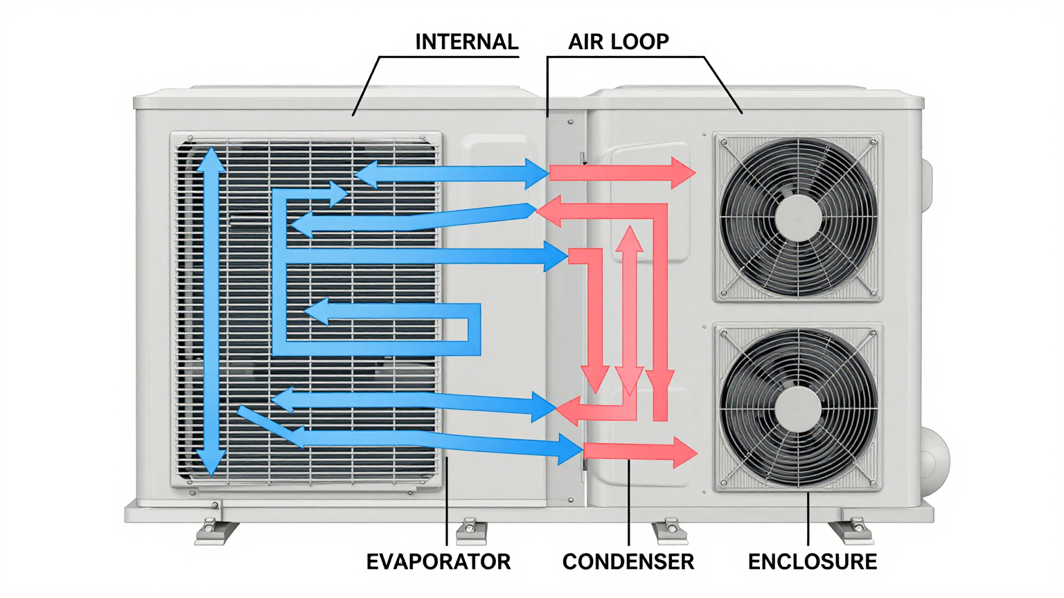
To make the right selection, we must understand the core principle of closed-loop cooling. A micro DC aircon operates by creating two completely separate air paths, which is the key to maintaining a perfect seal. The internal loop draws warm air from inside the enclosure, passes it over a cold evaporator coil to remove heat and moisture, and then returns the cool, dry air back into the enclosure. The heat absorbed by the evaporator is then transferred via refrigerant to an external condenser coil, where a second fan dissipates it into the ambient environment. This mechanism actively pumps heat out of the sealed box without ever mixing internal and external air.
This leads us to a critical engineering misconception.
Misconception: “More cooling capacity (BTUs or Watts) is always a safer choice. I should oversize the unit to be safe.”
Correction: Oversizing a vapor-compression air conditioner can be just as detrimental as undersizing it. An excessively powerful unit will cool the enclosure’s air volume too quickly, satisfying the thermostat and shutting off. This rapid on/off behavior, known as short-cycling, is highly inefficient. More importantly, it fails to adequately dehumidify the air. The unit doesn’t run long enough to pull significant moisture out of the air, which can then condense on cool surfaces when the temperature fluctuates. A correctly sized unit runs for longer, more stable cycles, effectively managing both temperature (sensible heat) and humidity (latent heat). This is a primary reason why a variable-speed micro DC aircon is often superior, as it can modulate its output to precisely match the heat load, avoiding inefficient short-cycling.
Key Specifications: The Starting Point
While a full thermal audit is necessary for final selection, the process begins by understanding the core specifications of available units. These numbers represent the go/no-go gates for your design. When evaluating a miniature DC air conditioner, focus on these primary parameters as your first filter. The table below shows example configurations for the Micro DC Aircon series.
| Model (Example) | DC Voltage | Nominal Cooling Capacity | Refrigerant |
|---|---|---|---|
| DV1910E-AC (Pro) | 12V | 450W | R134a |
| DV1920E-AC (Pro) | 24V | 450W | R134a |
| DV1930E-AC (Pro) | 48V | 450W | R134a |
| DV3220E-AC (Pro) | 24V | 550W | R134a |
How to interpret these specs for your decision:
- DC Voltage: This is a hard constraint. The unit’s voltage must match your system’s available power bus (e.g., 12V for vehicle-mounted systems, 24V for standard industrial automation, or 48V for telecommunications infrastructure).
- Nominal Cooling Capacity: This is the cooling power under specific, standardized test conditions. Crucially, this value must be derated based on your maximum expected ambient temperature. Always consult the manufacturer’s performance curve, which shows how capacity decreases as the ambient temperature rises.
- Refrigerant: While an important factor for regulation and environmental policy (e.g., R134a, R290), this is typically a fixed parameter for a given model and is secondary to the performance metrics for initial selection.
Engineering Selection Matrix: A 3-Gate Framework
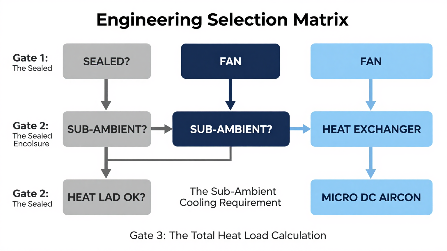
A robust selection process follows a series of logical gates. If your application fails to pass any of these gates, the type of required cooling technology changes. This framework forms the core of a reliable micro DC air conditioner selection guide.
Gate 1: The Sealed Enclosure Mandate
- Constraint Gate: Required NEMA/IP Rating vs. Environmental Contaminants.
- Decision Trigger: If the operating environment contains dust, moisture, oil, salt spray, or other airborne contaminants, and the enclosure must maintain a sealed integrity (e.g., NEMA 4, NEMA 12, NEMA 4X, or IP66).
- Engineering Resolution: All open-loop cooling solutions, such as filtered fans or simple vents, are immediately disqualified. These solutions inherently compromise the seal. The choice is now narrowed to closed-loop systems: either a passive heat exchanger or an active air conditioner.
- Integration Trade-off: This decision carries a higher upfront component cost compared to a fan. However, it virtually eliminates the risk of contamination-related failures and the associated high costs of downtime and maintenance.
Gate 2: The Sub-Ambient Cooling Requirement
- Constraint Gate: Required Internal Temperature vs. Maximum Ambient Temperature.
- Decision Trigger: If the maximum allowable internal temperature for your electronics is at or below the maximum expected external ambient temperature. For example, if your components must stay below 40°C, but the ambient air can reach 45°C.
- Engineering Resolution: A passive heat exchanger is now disqualified. Heat exchangers work by creating a large surface area for heat to transfer, but they rely on the ambient air being cooler than the internal air. They cannot cool below the ambient temperature. To achieve a sub-ambient internal state, you require an active, refrigerant-based vapor-compression system like a micro DC aircon, which functions as a heat pump.
- Integration Trade-off: This moves the solution from a passive device to an active one, introducing a significant DC power load from the compressor and fans. The system’s power budget must be designed to accommodate this. In return, you gain deterministic control over the internal thermal environment, independent of ambient conditions.
Gate 3: The Total Heat Load Calculation
- Constraint Gate: Required Cooling Capacity vs. Total System Heat Load.
- Decision Trigger: Once the total heat load is calculated, this value must be comfortably below the cooling unit’s rated capacity. The total heat load is the sum of two key figures: 1) The internal heat load (the power dissipated as heat by all components inside the enclosure), and 2) The external heat load (heat gained from the environment, primarily solar load on the enclosure’s outer surfaces).
- Engineering Resolution: This is the final step in DC enclosure air conditioner sizing. You must select a unit whose performance curve shows sufficient cooling capacity at your worst-case (highest) ambient temperature. For example, if your total heat load is 350W and your max ambient is 50°C, you need a unit that can provide more than 350W of cooling at that specific temperature, not just at its nominal 25°C rating.
- Integration Trade-off: Selecting a higher-capacity unit to meet this demand may increase the physical footprint, weight, and power draw. This requires careful mechanical and electrical planning to ensure the unit can be physically integrated and adequately powered.
Implementation & Verification Checklist
Proper selection is only half the battle. Correct installation is critical to realizing the performance and reliability of your chosen solution.
- Mechanical Integration
- Mounting Surface: Ensure the enclosure wall is flat, rigid, and strong enough to support the unit without flexing, which could compromise the seal.
- Gasket Seal: Clean the mounting surface thoroughly before applying the gasket. Tighten mounting bolts in a star pattern to the manufacturer’s recommended torque to ensure even pressure and a watertight seal.
- Airflow Integrity: Verify that there are no obstructions blocking the inlet and outlet vents for both the internal and external air loops. Respect the minimum clearance distances specified in the installation manual.
- Electrical Integration
- Power Supply: Confirm your DC power source can handle the unit’s peak inrush current on startup, which can be significantly higher than its steady-state running current.
- Overcurrent Protection: Install an appropriately rated fuse or circuit breaker on the power line as close to the power source as possible.
- Wiring: Use the correct wire gauge to minimize voltage drop over the required distance. Double-check polarity and ensure all electrical connections are secure and insulated.
- Thermal Validation
- Sensor Placement: Install an independent temperature and humidity sensor inside the enclosure to verify performance. Place it near the most heat-sensitive components and away from the direct output of the cold air stream for an accurate reading of the bulk internal temperature.
- Acceptance Testing: After installation, run the entire system under full electrical load on a warm day (or in a controlled thermal chamber) to confirm that the micro DC aircon can maintain the target temperature and that it cycles correctly.
Frequently Asked Questions (FAQ)
What is the first thing I need to measure for DC enclosure air conditioner sizing?
Two numbers are paramount: the total internal heat load (in watts) from all your electronics, and the maximum expected ambient temperature at the deployment site. Without these, any sizing calculation is a guess.
Should I choose a fan, a heat exchanger, or a micro DC aircon?
If your enclosure doesn’t need to be sealed from the environment, a fan may suffice. If it must be sealed but you can tolerate internal temperatures rising above ambient, a heat exchanger is an option. If it must be sealed AND you need to cool below the ambient temperature, a micro DC aircon is the required solution.
How do I manage condensation inside a sealed cabinet?
Proper sizing is the best defense. A correctly sized unit will run in longer cycles, effectively removing humidity. An oversized unit will short-cycle and can exacerbate condensation issues. Additionally, ensure the enclosure seal is perfect to prevent humid ambient air from entering.
My enclosure is in direct sunlight. How does that affect sizing?
You must calculate the solar heat load and add it to your internal heat load. This depends on the enclosure’s surface area, color, and the intensity of solar radiation. This can be a significant heat source and is a common reason for undersizing a cooling unit.
What if my environment is very dusty or corrosive?
In this case, a closed-loop cooling system is mandatory. A micro DC aircon is ideal because it maintains the NEMA/IP rating of your enclosure, completely isolating your sensitive electronics from the harsh external environment.
How do I validate the cooling performance after installation?
The best method is to use an independent data logger to monitor the internal temperature and humidity under real-world, full-load conditions. Compare this data against your design specifications to confirm the system is performing as expected.
Conclusion: Matching the Tool to the Task
A micro DC aircon is a specialized engineering tool. It is the definitive solution when two conditions are met: the electronics enclosure must remain sealed against the environment, and the internal temperature must be maintained at or below the external ambient temperature. For applications that don’t require a seal or sub-ambient cooling, simpler solutions may be adequate. But for rugged, mission-critical deployments in telecommunications, industrial automation, or outdoor kiosks, protecting the system’s integrity with a closed-loop, active thermal solution is a direct investment in reliability and uptime.
The complexities of a complete thermal audit—factoring in solar load, humidity, altitude, and unique enclosure geometries—often require a more detailed analysis. If you are working through a micro DC air conditioner selection guide for your next project, contact our engineering team. We can assist with precise sizing, customization for unique power or mounting constraints, and ensuring your thermal management system is perfectly matched to your application’s demands.