
Why a Miniature Air Conditioner Module Changes the OEM Design Equation
If you are an OEM product manager or mechanical engineer tasked with adding active cooling to an enclosed product, you already know the constraints: tight envelopes, DC power buses, weight budgets, and certification timelines that never seem long enough. A miniature air conditioner built around a BLDC variable-speed compressor can solve the thermal problem without forcing a complete redesign of your chassis. RIGID’s Micro DC Aircon series spans 450 W to 900 W of cooling capacity across eight models, all running natively on 12 V, 24 V, or 48 V DC. Each unit ships pre-charged with refrigerant, weighs roughly 5 kg (11 lbs), and occupies a footprint small enough to fit inside a telecom cabinet side panel.
This guide walks through the full integration path: selecting the right model for your thermal load, mounting the unit correctly, wiring it into your DC bus, choosing a speed-control interface, and avoiding the mistakes that add weeks to a prototype cycle.
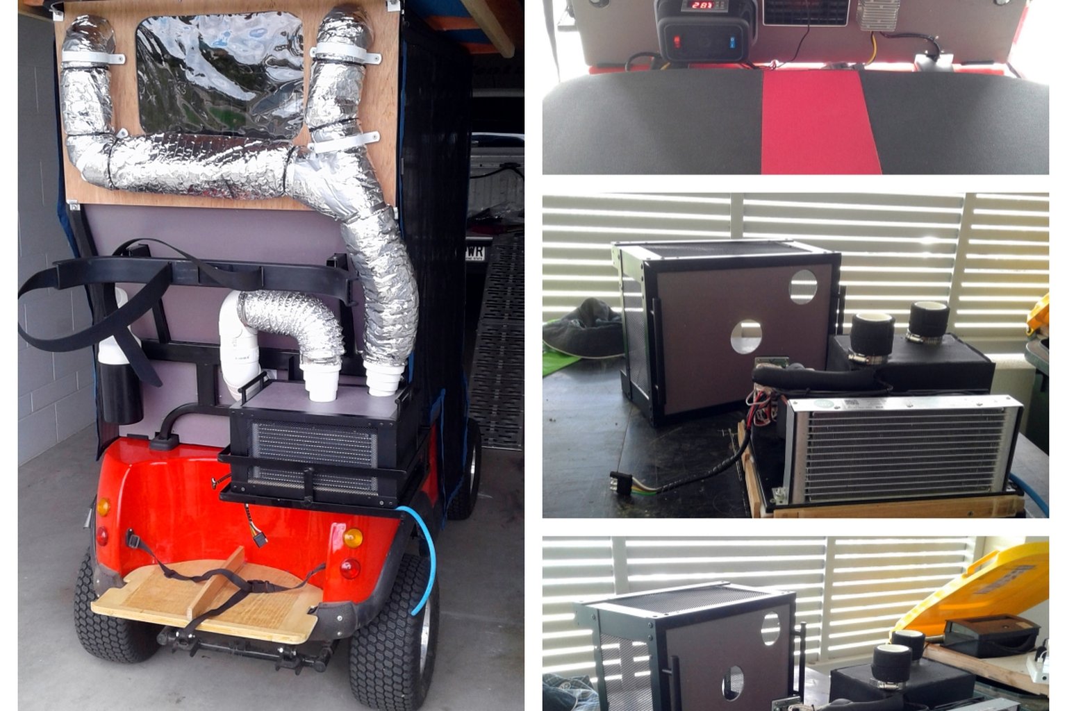
Typical OEM Integration Challenges
Before diving into selection and installation, it helps to name the five recurring challenges that OEM teams face when embedding active refrigeration into a product for the first time.
Space. Traditional split-system air conditioners assume wall-mount or window-mount clearances that simply do not exist inside a kiosk, a medical cart, or a battery enclosure. A miniature air conditioner module must fit within the product envelope alongside electronics, wiring harnesses, and structural members.
Power. Many OEM products run on a DC bus — 12 V in vehicles, 24 V in industrial equipment, 48 V in telecom racks. Converting to AC just to run a compressor wastes energy in the inverter and adds a failure point. DC-native compressors eliminate that conversion loss entirely.
Heat rejection. Every watt of cooling capacity you move from the conditioned space must be dumped somewhere else. If the condenser airflow path is blocked or undersized, the system high-side pressure rises, capacity drops, and compressor life shortens.
Vibration. Reciprocating compressors generate periodic forces that can loosen fasteners, fatigue sheet metal, and create audible noise. BLDC rotary compressors produce lower vibration amplitudes, but mounting compliance still matters.
Certification. Depending on your end market, you may need UL, CE, or other regional approvals. Using a pre-charged, factory-sealed refrigerant circuit simplifies the certification scope because the OEM does not need to qualify field brazing or charging procedures.
Model Selection: Matching Thermal Load, Voltage, and Refrigerant
RIGID offers eight standard models in the Micro DC Aircon-Cool line. The selection decision comes down to three variables: how much heat you need to remove, what DC voltage your bus provides, and whether your market requires a low-GWP refrigerant.
Step 1 — Quantify the Heat Load
Measure or calculate the total heat dissipation inside the enclosure under worst-case operating conditions. Include component waste heat, solar gain if the product is outdoors, and any heat conducted through the enclosure walls. Add a margin of roughly 15–20 % (this is an experience-based guideline, not a fixed standard) to account for degraded condenser performance at elevated ambient temperatures.
Step 2 — Match Capacity to a Model
| Model | Cooling Capacity | Voltage | Refrigerant |
|---|---|---|---|
| DV1910E-AC | 450 W (1,535 BTU) | 12 V | R134a |
| DV1920E-AC | 450 W (1,535 BTU) | 24 V | R134a |
| DV1930E-AC | 450 W (1,535 BTU) | 48 V | R134a |
| DV3220E-AC | 550 W (1,876 BTU) | 24 V | R134a |
| DV2820E-AC | 700 W (2,387 BTU) | 24 V | R134a |
| DV2820E-AC-T | 700 W (2,387 BTU) | 24 V | R290 |
| DV3820E-AC | 900 W (3,069 BTU) | 24 V | R134a |
| DV3830E-AC | 900 W (3,069 BTU) | 48 V | R134a |
If your heat load falls between two capacity tiers — say 600 W — choose the next size up (DV2820E-AC at 700 W). Running a slightly oversized unit at reduced compressor speed is more efficient and quieter than running a smaller unit at full speed continuously.
Step 3 — Voltage and Refrigerant
Most industrial and vehicle platforms standardize on 24 V, which gives you the widest model selection. If your bus is 12 V, the DV1910E-AC is the only standard option at 450 W; for higher capacities on a 12 V bus, contact RIGID engineering for custom configurations. For 48 V telecom or solar applications, the DV1930E-AC (450 W) and DV3830E-AC (900 W) are available.
On refrigerant: R134a covers most global markets today. If your product ships to the EU or other regions adopting low-GWP mandates, the DV2820E-AC-T uses R290 (propane), which has a GWP of 3 compared to R134a’s 1,430. R290 units require attention to charge limits and ventilation per IEC 60335-2-89 or equivalent local standards.
Mechanical Integration: Mounting, Airflow, and Drainage
Getting the mechanical integration right is where most first-time OEM integrators spend the majority of their prototype time. Three areas deserve close attention.
Mounting Orientation
The compressor in these units is a hermetic rotary type lubricated by oil that pools at the bottom of the shell. RIGID units are designed to operate in the orientation specified on the installation drawing — typically with the compressor upright or tilted no more than 15° from vertical (experience-based guideline). Mounting the unit on its side or inverted without confirming with RIGID engineering can starve the compressor of oil and lead to premature wear.
Secure the unit to a structural member using vibration-isolating mounts. Rubber grommets or silicone standoffs with a durometer of 40–60 Shore A work well for most enclosure materials. Avoid rigid metal-to-metal contact, which transmits compressor vibration directly into the chassis.
Condenser Airflow
The condenser (hot side) rejects heat to the ambient environment. It needs a clear, unobstructed airflow path. As a practical guideline, maintain at least 50 mm of clearance on the inlet and outlet sides of the condenser coil. If your enclosure forces the condenser air to turn corners, add ducting and verify that the pressure drop does not reduce airflow below the minimum specified in the model datasheet.
In outdoor products exposed to dust, pollen, or debris, install a washable filter upstream of the condenser. A clogged condenser is the single most common cause of reduced cooling performance in field-deployed units.
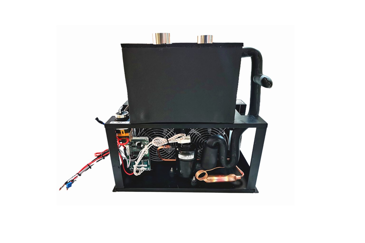
Condensate Drainage
When the evaporator cools air below its dew point, water condenses on the coil fins. This water must drain away from electronics and structural components. Route the drain line to the lowest point of the evaporator tray and ensure a continuous downward slope to the enclosure exit. In mobile applications subject to tilt and vibration, consider a small condensate pump or a larger-diameter drain fitting that tolerates partial blockage.
Electrical Integration: DC Wiring and Speed Control
Electrical integration is straightforward, but a few details matter for reliability and controllability.
DC Power Wiring
Each unit draws current from the DC bus through two power leads. Wire gauge must be sized for the maximum current draw of the selected model — for example, the DV3820E-AC at 24 V can draw up to approximately 10.3 A continuous (12.5 A peak). Use appropriately rated wire and include an inline fuse or circuit breaker sized to the peak current rating. Keep power leads as short as practical to minimize voltage drop; a drop exceeding 5 % of the nominal bus voltage can cause the drive board to fault or reduce compressor speed.
If your product uses a battery bus, verify that the battery management system (BMS) can handle the inrush current at compressor startup. BLDC variable-speed compressors have a soft-start characteristic that limits inrush, but the initial current spike is still higher than steady-state draw.
Speed Control Interface
RIGID units support four speed-control signal types, giving you flexibility to match your existing control architecture:
- Potentiometer — simplest option; a manual knob or a digitally controlled potentiometer sets compressor speed. Good for products where the end user adjusts cooling manually.
- 0–5 V analog — your host controller outputs a voltage proportional to desired speed. Ideal for closed-loop temperature control where a microcontroller reads a thermistor and adjusts the signal.
- PWM — a pulse-width-modulated signal controls speed. Common in automotive and industrial control systems where PWM buses already exist.
- TTL serial — digital communication for systems that need precise speed commands and status feedback. Useful when your product’s main controller needs to log compressor RPM or fault codes.
Choose the interface that matches your existing control hardware. If you are building a new controller from scratch, the 0–5 V analog interface offers the best balance of simplicity and precision for closed-loop temperature regulation.
Common Integration Mistakes and How to Avoid Them
After working with OEM integrators across telecom, medical, and vehicle markets, several recurring mistakes stand out. Addressing them early saves prototype iterations.
Undersizing the condenser airflow path. Engineers often allocate generous space for the evaporator (cold side) because it faces the payload, then squeeze the condenser into whatever space remains. The condenser needs equal or greater airflow attention. Restricted condenser airflow raises discharge pressure, reduces capacity, and increases power consumption.
Ignoring condensate in sealed enclosures. If your enclosure is IP65 or higher, the condensate has nowhere to go unless you provide a drain path. Water pooling inside a sealed enclosure will eventually reach electronics. Design the drain routing before finalizing the enclosure sealing strategy.
Running power leads through high-EMI zones. The compressor drive board switches current at high frequency. Route the DC power leads away from sensitive analog signal lines and RF circuits. If crossing is unavoidable, use shielded cable or maintain at least 50 mm of separation.
Skipping thermal testing at elevated ambient. A miniature air conditioner rated at 700 W will not deliver 700 W of cooling if the ambient temperature at the condenser inlet is 50 °C instead of the rated 35 °C. Always test at the highest ambient temperature your product will encounter in the field.
Forgetting compressor orientation during drop testing. If your product undergoes shock and vibration qualification, verify that the compressor mounting survives the test profile without shifting orientation. A compressor that tilts beyond its allowable angle after a drop event may fail in the field.
Application Boundaries: Where These Modules Fit — and Where They Do Not
Understanding the operating envelope prevents misapplication and field failures.
Well-Suited Applications
- Telecom cabinets and outdoor electronics enclosures running on 24 V or 48 V DC
- Medical devices and diagnostic equipment requiring precise temperature control between 5 °C and 30 °C
- Battery thermal management in electric vehicles and energy storage systems
- Laser and optics cooling where stable temperature prevents wavelength drift
- Mobile command posts, drone docking stations, and field-deployed military electronics
- Vending machines, kiosks, and compact retail refrigeration
Not the Right Fit
- Large spaces requiring more than 900 W (3,069 BTU) of cooling — these modules are not designed to scale by simply adding multiple units in parallel without engineering review
- Applications requiring cooling below 5 °C — these are air conditioning modules, not freezers
- Environments with sustained ambient temperatures above 55 °C at the condenser inlet — high-side pressure limits will reduce capacity significantly
- Products that require AC-powered operation with no DC bus available — an external AC-to-DC power supply adds cost, size, and a failure point that may negate the advantages of a DC-native module
Getting Started: From Sample to Production
RIGID supports OEM integration from the earliest prototype stage. The minimum order quantity for evaluation samples is one unit, so you can validate fit, thermal performance, and electrical integration before committing to production volumes. For detailed specifications, CAD models, and application engineering support, visit the Micro DC Aircon product page on the RIGID HVAC site.
Start with your heat load calculation, match it to a model from the table above, and request a sample. Most OEM integrators complete mechanical and electrical integration within two to three prototype cycles — faster when the condenser airflow and condensate drainage are addressed in the first CAD revision rather than discovered during thermal testing.
A well-integrated miniature air conditioner module disappears into your product. Your customer sees reliable temperature control; your engineering team sees a sealed, pre-charged refrigerant circuit that required no field brazing, no inverter, and no compromise on the product envelope. That is the point of choosing a DC-native, variable-speed module built for OEM embedding from the start.