
Miniature Refrigeration Condensing Unit: Building the Cooling Engine Before the Enclosure
The product design is nearly finished. The industrial designer has locked the outer shell dimensions, the PCB layout is frozen, and the first injection-mold quotes are in. Then someone asks: where does the cooling system go? The compressor, condenser, evaporator, and fan assembly that seemed like minor line items on the BOM turn out to need more volume than the remaining cavity can offer. This is the moment when a miniature refrigeration condensing unit stops being a catalog search and becomes a critical-path engineering decision.
The pattern repeats across custom mini-fridges, portable medical coolers, compact wine cabinets, and benchtop laboratory chillers. The enclosure form factor is defined by the end-use context, not by the refrigeration hardware. The cooling system must conform to the available space, not the other way around. This article covers the integration approach for OEM teams that need to embed a condensing unit into a form factor that was designed without one.
Why the Cooling System Is Usually the Last Thing That Fits
In consumer and commercial product development, the exterior design drives the timeline. Market research defines the size, shape, and aesthetic. Mechanical engineering allocates internal volume for the payload (food, samples, bottles), electronics, insulation, and structural elements. The refrigeration system gets whatever space remains, which is often a narrow L-shaped cavity behind the liner or a shallow compartment under the base.
This is not poor planning. It reflects the reality that the product’s value proposition is defined by its external form and payload capacity, not by its compressor. But it creates a constraint that off-the-shelf condensing units rarely satisfy. Standard units are designed for standard enclosures. A custom product with a curved back panel, a tapered base, or an asymmetric internal layout needs a condensing unit that fits the geometry, not one that dictates it.
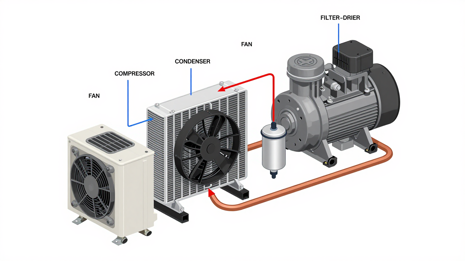
The core insight is architectural: treat the condensing unit as the cooling engine and design the refrigeration system around it, adapting the condenser shape, evaporator routing, and airflow path to the available volume. The compressor and its immediate components (accumulator, filter-drier, service valves) form a compact core that can be oriented and positioned to fit irregular cavities. The condenser and evaporator are the flexible elements whose geometry can be customized to fill the remaining space efficiently.
Anatomy of a Miniature Condensing Unit
A condensing unit in the miniature refrigeration context typically includes:
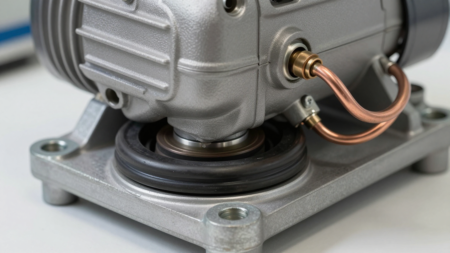
- A DC brushless compressor, usually rotary type, operating on 12 V, 24 V, or 48 V. The compressor is the fixed-geometry element. Its diameter, height, and mounting pattern define the minimum cavity dimensions.
- An air-cooled condenser coil with an integrated fan. This is the component most often customized for OEM applications. The coil can be shaped as a flat panel, an L-bend, or a U-wrap to conform to the available airflow path.
- A filter-drier and capillary tube or electronic expansion valve, connecting the high-pressure and low-pressure sides of the circuit.
- Pre-charged refrigerant (typically R134a or R600a), factory-sealed so the OEM does not need refrigeration technicians on the assembly line.
The evaporator is usually supplied separately because its form factor depends entirely on the payload chamber design. Plate evaporators bond directly to the liner wall. Tube-on-sheet evaporators wrap around cylindrical chambers. Finned coil evaporators sit in an air duct. The condensing unit manufacturer provides the high-pressure half of the system; the OEM integrates the low-pressure half to match their specific geometry.
Fitting the Engine: Airflow Is the Real Constraint
Engineers often focus on physical dimensions when evaluating whether a condensing unit fits. Will the compressor clear the back panel? Does the condenser fit in the base compartment? These are necessary checks but not sufficient. The real constraint is airflow.
A condenser that fits physically but cannot breathe will overheat. The compressor discharge pressure rises, the condensing temperature climbs, and the system loses cooling capacity. In severe cases, the high-pressure switch trips and the unit shuts down. This failure mode is invisible during bench testing with the enclosure panels removed but appears immediately in the assembled product.
The minimum airflow requirement depends on the condensing capacity and the allowable temperature rise across the condenser. For a typical miniature unit with 100 to 300 watts of cooling capacity, the condenser fan needs to move roughly 30 to 80 cubic feet per minute (CFM) of air across the coil. The enclosure must provide inlet and outlet openings sized to support this flow without excessive pressure drop.
Common airflow mistakes in compact enclosures:
- Inlet grilles with decorative patterns that look open but restrict flow by 40 to 60 percent compared to the gross opening area.
- Condenser compartments with no defined outlet path, forcing hot air to recirculate back through the coil.
- Fan placement that pushes air against a wall or into a dead-end cavity instead of through the condenser core.
- Insufficient clearance between the condenser face and the nearest obstruction, creating a high-velocity zone that increases noise without improving heat transfer.
The fix is to design the airflow path before finalizing the enclosure geometry. Define the inlet, the condenser position, the fan location, and the outlet as a continuous channel. If the channel has turns, add radius to the corners. If the outlet is on a different face than the inlet, ensure the cross-sectional area does not pinch below the condenser face area at any point along the path.
Vibration and Noise: Living with a Compressor Inside the Product
A condensing unit mounted inside a consumer or commercial product must meet noise and vibration expectations that industrial equipment ignores. A mini-fridge in a hotel room, a wine cabinet in a living room, or a medical cooler in a clinic cannot sound like a workshop compressor.
DC brushless compressors are inherently quieter than AC reciprocating types, but they still generate vibration at the rotational frequency and its harmonics. The vibration transmits through the mounting points into the enclosure structure, which can amplify certain frequencies and radiate them as audible noise. A compressor that measures 35 dBA on a test bench can produce 45 dBA or more when hard-mounted to a thin sheet-metal enclosure that resonates at the compressor’s fundamental frequency.
Isolation mounting is essential. Rubber grommets or silicone pads between the compressor feet and the enclosure structure attenuate vibration transmission. The isolator stiffness should be chosen so that the natural frequency of the compressor-on-isolator system is well below the compressor’s operating speed range. For a compressor running between 2,000 and 4,500 RPM, isolators with a natural frequency below 15 Hz provide effective attenuation across the full speed range.
Refrigerant tubing that connects the compressor to the condenser and evaporator also transmits vibration. Flexible sections or service loops in the tubing near the compressor decouple the vibration path. Hard copper tubing brazed directly from the compressor discharge to a rigidly mounted condenser creates a vibration bridge that bypasses the isolator mounts entirely.

Thermal Interference: Keeping the Hot Side Away from the Cold Side
In a full-size refrigerator, the condenser is on the back or bottom and the evaporator is inside the cabinet, separated by insulation and distance. In a miniature product, the condenser and evaporator may be centimeters apart, separated by a thin insulation layer. Heat conducted or radiated from the condenser to the evaporator side reduces net cooling capacity and increases energy consumption.
Thermal interference is the silent efficiency killer in compact refrigeration products. It does not cause dramatic failures. It simply makes the compressor run longer and harder to maintain the same cabinet temperature, increasing power consumption and shortening compressor life. In battery-powered products, it directly reduces runtime.
Mitigation strategies:
- Route the hot discharge line away from the evaporator and insulated walls. A discharge line touching the cabinet liner transfers heat directly into the cooled space.
- Add a thermal barrier (foam strip or air gap) between the condenser compartment and the insulated cabinet wall.
- Ensure the condenser airflow path exhausts to the exterior, not into the space between the liner and the outer shell where it would heat the insulation from outside.
Selecting the Right Unit: Capacity Matching for Small Volumes
Oversizing a condensing unit for a miniature application is as problematic as undersizing. An oversized compressor short-cycles: it reaches the target temperature quickly, shuts off, and restarts when the temperature drifts up. Each start-stop cycle stresses the compressor motor and valves, wastes energy during the startup transient, and creates temperature fluctuations in the payload.
The correct approach is to calculate the steady-state heat load of the enclosure (wall conduction, door openings, payload heat, ambient conditions) and select a condensing unit whose capacity at the design conditions matches or slightly exceeds that load. Variable-speed DC compressors help enormously here because they can modulate capacity down to 30 to 50 percent of their rated maximum, reducing short-cycling at low loads while still handling peak demand.
For OEM applications where the enclosure design is fixed and the operating conditions are well defined, the condensing unit manufacturer can optimize the refrigerant charge, capillary tube length, and fan speed to match the specific application. This application-specific tuning extracts performance that a generic off-the-shelf unit cannot match, because the factory calibration accounts for the actual airflow path, insulation thickness, and thermal load profile of the target product.
Frequently Asked Questions
Can I use a standard condensing unit in a custom enclosure?
Sometimes, if the available cavity matches the unit’s dimensions and airflow requirements. But in most custom products, the geometry mismatch between standard units and the available space leads to compromised airflow, excessive noise, or wasted volume. A unit configured for the specific application typically delivers better performance in less space.
What refrigerant is best for miniature condensing units?
R134a and R600a (isobutane) are the most common choices. R134a offers broad compatibility and well-understood performance. R600a provides higher thermodynamic efficiency and lower environmental impact but requires compliance with flammability standards. The choice depends on the target market’s regulatory requirements and the OEM’s manufacturing capabilities for handling flammable refrigerants.
How do I specify the evaporator if it is not included with the condensing unit?
The condensing unit manufacturer provides the required evaporator capacity, refrigerant connection sizes, and superheat target. The OEM selects or designs an evaporator that meets these specifications while fitting the payload chamber geometry. Close coordination between the condensing unit supplier and the OEM mechanical team is essential to ensure the system balance is correct.
What is the typical lead time for a custom-configured condensing unit?
Initial samples with application-specific tuning typically require four to eight weeks from specification agreement. Production quantities follow standard manufacturing lead times, usually six to twelve weeks depending on volume and component availability.
Does the condensing unit come pre-charged with refrigerant?
Yes, in most OEM configurations. The unit ships factory-sealed with the correct refrigerant charge for the specified evaporator and operating conditions. The OEM assembly process involves mechanical mounting and electrical connection only, with no refrigerant handling required on the production line.
How does variable-speed operation affect noise levels?
Variable-speed DC compressors run at lower speeds under partial load, which reduces both vibration amplitude and acoustic noise. At minimum speed, noise levels can drop significantly compared to full-speed operation. Since most operating hours occur at partial load, the average noise level over a duty cycle is substantially lower than the peak rating.
Building Around the Cooling Engine
The most successful miniature refrigeration products treat the condensing unit as a core subsystem that deserves early attention in the design process, not as a commodity component to be sourced after the enclosure is finalized. When the cooling engine is selected and its airflow, vibration, and thermal interference requirements are understood before the enclosure geometry is locked, the integration is straightforward. When it is an afterthought, the result is compromised performance, excessive noise, or a last-minute redesign that delays the program.
RIGID’s DC condensing unit range is designed for exactly this integration model: compact cores with configurable condenser geometry, pre-charged refrigerant circuits, and application-specific tuning that matches the unit to the OEM’s enclosure and operating conditions.
If your enclosure geometry, payload requirements, or operating conditions present constraints that standard catalog units cannot accommodate, the engineering team can review your layout and recommend a configuration path that fits the available space while meeting the thermal performance target.