
Why Photoreactor Cooling Has Two Separate Jobs
Photochemistry uses light to drive reactions that heat alone would not run cleanly. Modern photoreactors use high-power LEDs or lamps close to the reaction vessel, and they are remarkably inefficient heaters of everything around them. Most of the electrical power that goes into a light source ends up as heat, and some of the light that reaches the reaction is absorbed and turns into heat there too.
That creates two different cooling problems. The light source needs its heat carried away so its output and lifetime stay stable. The reaction needs its temperature held, often at or below room temperature, because selectivity and side reactions depend on it. Good photoreactor cooling treats these as separate duties, even when one chiller serves both.
This guide shows where the heat comes from, works through a heat budget for an LED photoreactor, compares single-loop and two-loop layouts, covers condensation and light-path details, and explains where a compact liquid chiller module fits.
Where the Heat Comes From
| Source | Where the heat appears | Notes |
|---|---|---|
| LED or lamp electrical losses | At the light source and its heat sink | Usually the largest share of the power |
| Light absorbed by the reaction and vessel | In the reaction mixture and glass | Grows with light intensity and absorbance |
| LED drivers and power supplies | In the electronics housing | Often air-cooled, but adds to the enclosure temperature |
| Stirring | In the reaction | Small, but continuous |
| Reaction enthalpy | In the reaction | Depends entirely on the chemistry |
| Room heat gain | Vessel, hoses and fittings | Grows as the set point falls below room temperature |
Two of these tend to surprise people. The light itself becomes heat once it is absorbed, so a brighter photoreactor warms its reaction faster. And LED arrays commonly include thermal protection that reduces output or switches off if the heat sink gets too hot, so inadequate cooling can quietly lower the light dose rather than simply raise a temperature reading.
Measure rather than guess where you can. The electrical input to the LED drivers is easy to log, and a short warm-up test on the reaction side, run with solvent or another non-reacting load, the light on and cooling paused, shows how quickly the contents heat. Those two numbers give a far better starting point for photoreactor cooling than any rule of thumb.
Worked Heat Budget for an LED Photoreactor
The example below uses assumed values for illustration: an LED photoreactor drawing 100 W of electrical power, a reaction held at 15 °C in a 22 °C laboratory, and a modest reaction exotherm.
| Heat load | Assumption | Where it must be removed | Heat |
|---|---|---|---|
| LED heat sink | About 70% of electrical input lost as heat at the source | LED cooling plate | About 70 W |
| Absorbed light | About 25 W of optical power absorbed in vessel and reaction | Reaction jacket or well | About 25 W |
| Stirring and reaction enthalpy | Small, steady contribution | Reaction jacket or well | About 10 W |
| Room gain at 15 °C | Vessel, hoses and fittings | Reaction loop | About 10 W |
| Total | Roughly 115 W |
 The worked budget shows why photoreactor cooling needs thinking about where the heat is, not just how much there is. About 70 W appears at a light source that can run comfortably warm, and about 45 W appears in a reaction that has to stay at 15 °C. Both have to be removed, but not at the same temperature.
Scale-up changes the balance. Doubling light power roughly doubles both the LED heat and the absorbed light, but a larger vessel has less jacket area per liter of reaction. Heat removal from the reaction usually becomes the limit before LED cooling does, which is one reason flow photoreactors with thin reaction channels are used at higher light intensities.
One Loop or Two
| Layout | Strengths | Limits |
|---|---|---|
| Single loop through LED plate and reaction jacket in series | Simplest plumbing, one set point | Coolant temperature is a compromise; the second component sees warmer fluid |
| Single chiller, two parallel branches | Both components get fresh coolant | Still one temperature; flow must be balanced between branches |
| Two loops at different set points | LEDs run warm and efficient, reaction held precisely | More equipment and control |
| Air-cooled LEDs, liquid-cooled reaction | Liquid loop only serves the reaction | Works only while LED heat can be rejected to air |
If one loop must serve both, put the reaction jacket first in the flow path so it receives the coldest coolant, and let the LED plate take the warmer return. Reversing the order sends LED heat straight into the reaction’s coolant. Series order does not solve condensation, though: if the coolant leaving the reaction jacket is still below the room’s dew point, the LED plate will collect water. Check that return temperature against the dew point before sharing a loop, and use two loops when it is too cold.
Whatever the layout, give each branch its own temperature reading. A single sensor at the chiller outlet cannot tell you that the LED plate is running hot or that the reaction jacket is starved of flow.
How Cold the Coolant Needs to Be
The reaction and the light source want different coolant temperatures, and running both as cold as possible is rarely right.
- The reaction sets the lower limit of useful coolant temperature. Coolant needs to be a few kelvin below the reaction set point to carry the heat away through the jacket or immersion well.
- The LED plate does not need cold coolant. LEDs tolerate a warm heat sink within their rating, and running the plate far below room temperature brings condensation onto electronics.
- Keep any coolant that reaches electrical parts above the room’s dew point. A reaction loop can run colder if its hoses and fittings are insulated and kept away from drivers and connectors.
- If the chemistry needs sub-zero temperatures, separate the loops, so the LED side is not dragged below the dew point.
The same thinking about keeping optical sources stable at a moderate coolant temperature appears in laser cooling; our guide to chillers for laser cooling covers that side.
Flow, Fittings and the Light Path
Photoreactors add a detail other cooling loops do not: coolant sometimes sits between the light and the reaction.
- In immersion-well designs, a coolant layer surrounds the lamp. Keep that coolant clean and free of deposits, bubbles and growth, since anything in the light path absorbs or scatters light.
- Check that jacket and well materials and the coolant suit the wavelengths used; some fluids and plastics absorb in the ultraviolet.
- Use flow that keeps LED plate temperature even across the whole array, so no LEDs run hotter than their neighbors.
- Route coolant bottom-in, top-out through jackets to purge trapped air, which otherwise creates warm spots.
- Choose fittings and hoses rated for the coolant and pressure, and secure them away from the light source and electronics.
Check flow again after the loop has run cold for a while. Coolant thickens as it cools, and a loop that looked fine at room temperature can deliver noticeably less flow to the LED plate at its working temperature.
Condensation and Electrical Safety
Photoreactors combine cold liquid, high-power electronics and often flammable solvents in a small space. That makes condensation a safety topic as well as a nuisance.
- Insulate cold hoses and fittings near the reactor and keep them away from drivers and power connections.
- Keep LED plate coolant above the dew point unless the electronics are designed and sealed for cold operation.
- Provide a drip path so any condensate or leak runs away from electrical parts.
- Interlock the light source with coolant flow where possible, so LEDs switch off if cooling stops.
- Check the photoreactor maker’s guidance on coolant temperature and pressure before connecting any external chiller.
Treat a coolant leak near the light source as a stop condition, not a nuisance: switch off the LEDs and the drivers before cleaning up, and find the cause before restarting.
Where a Compact Liquid Chiller Module Fits
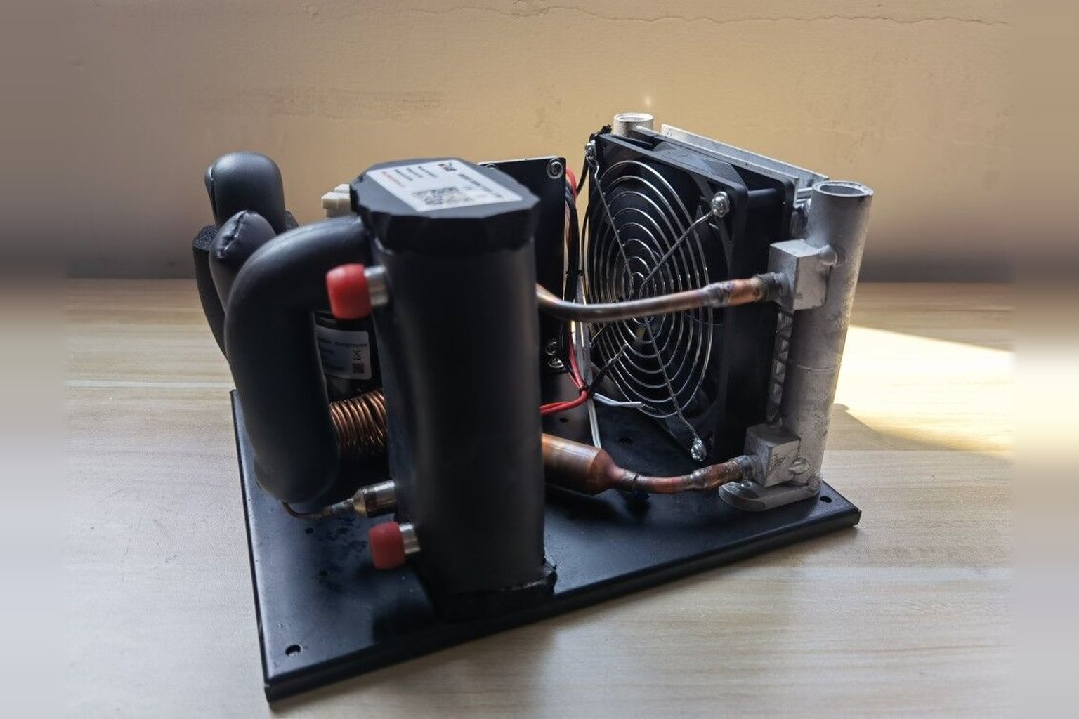
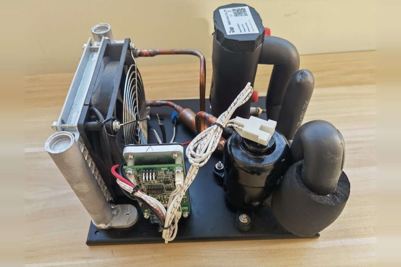 A compact liquid chiller module is a good fit when photoreactor cooling is built into an instrument or a reaction station, rather than supplied by a separate benchtop unit on the lab floor. Instrument builders use modules like these to put a controlled cooling loop inside the product.
RIGID’s Compact Liquid Chiller line (DV series) is listed at 100 to 550 W of cooling capacity, with a listed temperature range of ±20 °C, 12V, 24V or 48V DC supply, and R134a or R290 refrigerant. It is offered with plate, coaxial, stainless steel coil and copper coil heat exchanger structures, for example the DV1910E-P plate version at 12V. Pump flow, pump head and the test conditions behind the capacity figures are not listed, and the product line includes configurations described with an external pump as well as integrated circulation, so confirm the pump, reservoir, controller and power supply included in the specific version. Because the modules run on DC, a benchtop installation also needs a suitable DC power supply and enclosure.
That listed range describes coolant temperatures, not reaction temperatures. Because a reaction runs warmer than its coolant, the coldest reaction a module can hold sits above its lowest coolant temperature by the jacket temperature difference at your heat load. Loops that need coolant colder than −20 °C, or heating above +20 °C, are beyond the listed range and need other equipment.
Sizing Checklist
- Split the heat budget into light-source heat and reaction heat, including absorbed light.
- Set the reaction coolant temperature from the chemistry, and the LED coolant temperature from the LED rating and dew point.
- Choose one loop, parallel branches or two loops based on how far apart those temperatures are.
- Check capacity at the actual coolant temperature, not only the nominal rating, with margin for warmer rooms. Our guide to small chiller sizing and set point derating explains why.
- Confirm flow and pressure at the LED plate and jacket, with the coolant at operating temperature.
- Plan insulation, drip paths and light-source interlocks before first use.
For the reaction side on its own, including estimating chemical heat release, see our guide to sizing a chiller for a lab reactor.
Common Mistakes
- Sizing photoreactor cooling for the LED heat and forgetting light absorbed in the reaction.
- Running LED plates far below room temperature and condensing water onto electronics.
- Plumbing the LED plate before the reaction jacket in a series loop.
- Letting deposits or bubbles build up in coolant that sits in the light path.
- Assuming LED output stays constant when thermal protection is quietly reducing it.
- Choosing a module by nominal capacity without checking capacity at the reaction coolant temperature.
If you are designing cooling for a photoreactor or reaction station, send us the light source power, reaction temperature, vessel and jacket design, supply voltage and space available, and our engineers will help work through the cooling loop. Send your photoreactor cooling details to our engineering team.
Frequently Asked Questions
Why does a photoreactor need cooling?
Most of the electrical power supplied to LEDs or lamps becomes heat, and light absorbed by the reaction also turns into heat. Without cooling, the light source can derate or fail and the reaction temperature drifts, which changes selectivity and side reactions.
Should the LEDs and the reaction share one cooling loop?
They can, if the reaction jacket is placed first in the flow path and the temperatures they need are close. When the reaction must run much colder than the LEDs, two loops at different set points usually work better and avoid condensation on electronics.
How much cooling does an LED photoreactor need?
In the worked example, a 100 W LED photoreactor with a reaction at 15 °C needed roughly 115 W removed: about 70 W at the LED plate and about 45 W at the reaction. Your own figures depend on light power, absorbance, chemistry and room conditions.
Can the LED cooling plate run below room temperature?
It can, but running it below the dew point causes condensation on electronics unless they are designed for it. LEDs generally do not need cold coolant; a moderate temperature within their rating is safer.
What coolant should be used in a photoreactor loop?
Use a coolant compatible with the jackets, fittings and chiller, with margin below the coldest set point. Where coolant sits in the light path, keep it clean and check that it does not absorb the wavelengths used.
What temperature range can a compact liquid chiller module cover for photochemistry?
RIGID’s DV-series modules are listed at ±20 °C for the coolant. A reaction runs warmer than its coolant, so the coldest reaction a module can hold depends on the heat load and the jacket. Coolant colder than −20 °C, or heating above +20 °C, is beyond the listed range.