
Point of Care Thermal Management: Why Field Diagnostics Need Active Cooling
Point of care thermal management has become a critical engineering challenge as diagnostic devices move from climate-controlled laboratories to ambulances, field clinics, disaster response units, and mobile health screening vehicles. These instruments — blood analyzers, PCR amplifiers, immunoassay readers, portable ultrasound systems — contain temperature-sensitive optics, reagents, and electronics that were originally designed for 20-25°C laboratory environments.
When deployed in the field, ambient temperatures can range from -10°C to 50°C depending on geography and season. Without active thermal management, measurement accuracy degrades, reagent shelf life shortens, and electronic components experience accelerated aging. The challenge is providing laboratory-grade temperature stability in a package that fits inside a portable instrument or vehicle-mounted cabinet.
Heat Sources in Point-of-Care Devices
Understanding the thermal loads in portable diagnostics equipment reveals why passive cooling is insufficient for point of care thermal management:
Optical systems: Laser diodes, LED excitation sources, and photodetectors in fluorescence-based analyzers generate 5-30W of concentrated heat. More critically, these components require temperature stability within ±0.5°C to maintain calibration accuracy. Wavelength drift in laser diodes is approximately 0.3 nm/°C — enough to shift fluorescence excitation peaks out of optimal range.
PCR thermal cyclers: Rapid heating/cooling cycles between 60°C and 95°C generate significant waste heat during the cooling phase. The Peltier elements used for cycling must reject heat to a stable thermal sink. If the sink temperature rises above 35°C, cooling rate decreases and cycle times extend — directly impacting time-to-result in urgent diagnostic scenarios.
Power electronics: DC-DC converters, battery charging circuits, and motor drivers in centrifuge-equipped analyzers contribute 20-80W of distributed heat. In sealed enclosures (required for IP65+ field ratings), this heat accumulates without active removal.
Reagent storage: Many immunoassay cartridges and blood chemistry reagents require storage between 2-8°C. In a vehicle parked in direct sun, interior temperatures can exceed 60°C within 30 minutes. Active cooling is not optional — it is the difference between valid and invalid test results.
Specific Diagnostic Device Thermal Requirements
Different categories of point-of-care instruments impose distinct thermal constraints that shape the cooling system design:
Hematology analyzers: These devices measure complete blood counts using impedance or optical scatter methods. The measurement chamber must maintain 22±3°C to ensure consistent blood viscosity during flow-through analysis. The laser scatter detector requires even tighter stability — ±1°C — to prevent baseline drift in cell differentiation algorithms. Total heat dissipation is typically 40-80W, concentrated in the optical block and processing electronics.
Lateral flow immunoassay readers: While the test strips themselves are passive, the optical reader (CCD or CMOS sensor with LED illumination) requires thermal stability for consistent quantitative results. Temperature-induced dark current changes in the image sensor create measurement noise that degrades limit-of-detection performance. These devices generate modest heat (15-30W) but require the ambient environment to remain within 18-28°C for validated accuracy claims.
Blood gas analyzers: Electrochemical sensors for pH, pCO2, and pO2 have temperature coefficients that must be compensated. While modern analyzers include internal temperature compensation algorithms, these algorithms are validated only within a specified ambient range (typically 15-32°C). Operating outside this range introduces uncharacterized errors. The sensor cartridge heating elements and calibration gas valves contribute 25-50W of internal heat generation.
Coagulation testing devices: Point-of-care INR and ACT analyzers use optical or mechanical clot detection methods that are sensitive to sample temperature. The test channel must maintain 37±0.5°C (body temperature) regardless of ambient conditions. In cold environments, this requires heating; in hot environments, the surrounding electronics must be cooled to prevent thermal crosstalk that would push the test channel above 37.5°C.
Why Passive Solutions Fail in Field Deployment
Laboratory instruments rely on building HVAC to maintain ambient conditions. Field-deployed point-of-care devices cannot make this assumption. The failure modes of passive thermal management in mobile applications include:
Heat sinks saturate: A finned aluminum heat sink sized for 25°C ambient reaches thermal equilibrium at a higher temperature when ambient rises to 45°C. The temperature differential driving convection decreases, and heat removal rate drops proportionally. The device overheats despite having “adequate” passive cooling for laboratory conditions.
Fans cannot cool below ambient: Forced-air cooling improves convective heat transfer but cannot reduce component temperatures below the incoming air temperature. In a 45°C environment, the best a fan can achieve is bringing components close to 45°C — still 20°C above the optimal operating range for many precision instruments.
Phase-change materials (PCM) are temporary: PCM packs absorb heat during their melting transition, providing a thermal buffer. But they are finite — once fully melted, they offer no further cooling. In continuous-operation scenarios (8-12 hour field shifts), PCM alone cannot maintain temperature without periodic regeneration.
DC Vapor Compression: The Engineering Case for Active Cooling
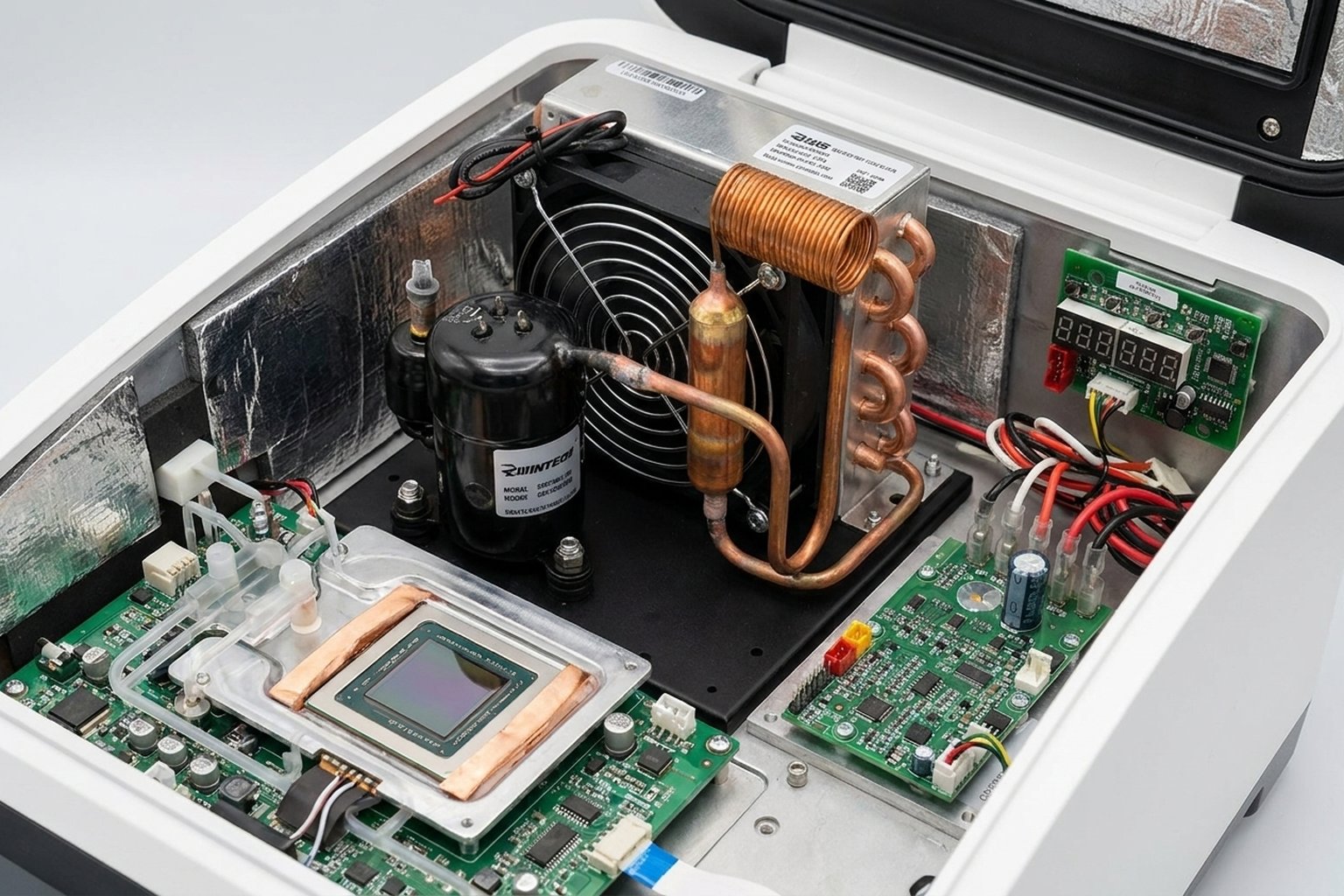
Compact DC vapor compression systems address the fundamental limitation of passive approaches: they can maintain temperatures below ambient indefinitely, powered by vehicle batteries or portable power systems. For point of care thermal management, the relevant specifications include:
- Cooling capacity: 450-900W depending on model selection (DV1910E through DV3820E series)
- Temperature differential: Up to 20°C below ambient in continuous operation
- Power source: 12V, 24V, or 48V DC — compatible with vehicle electrical systems and portable battery packs
- Weight: Approximately 5 kg for the complete cooling module
- Refrigerant: R134a (pre-charged, sealed system, no field servicing required)
- Compressor type: BLDC variable-speed, enabling precise temperature control through speed modulation
The variable-speed capability is particularly relevant for point-of-care applications. Rather than cycling on/off (which creates temperature oscillations), the BLDC compressor adjusts speed continuously to match the instantaneous heat load. This provides the ±1-2°C stability that sensitive instruments require.
Integration Architecture for Portable Medical Instruments
Point of care thermal management integration follows one of three architectural patterns depending on the instrument design:
Pattern 1: Enclosed cabinet cooling. The diagnostic device sits inside a thermally insulated cabinet (vehicle-mounted or portable case). The micro DC air conditioner maintains the entire cabinet at target temperature. This approach works well for multi-instrument setups where several devices share a common thermal environment. Cabinet volume should not exceed 200 liters for a 450W unit to maintain adequate temperature uniformity.
Pattern 2: Direct evaporator integration. The evaporator coil mounts directly against or within the instrument chassis, providing localized cooling to the highest-priority thermal zone. The condenser mounts externally. This approach maximizes cooling efficiency for single-instrument applications but requires closer mechanical integration with the device manufacturer.
Pattern 3: Liquid loop with chiller. For instruments requiring precise spot cooling (laser modules, reagent chambers), a compact liquid chiller circulates coolant through cold plates or jackets. The micro DC compressor drives the refrigeration cycle, and a small pump circulates the secondary coolant. This provides the highest precision but adds system complexity.
Power Budget for Mobile Deployment
Field deployment means finite power. Point of care thermal management must fit within the available electrical budget alongside the diagnostic instruments themselves:
Ambulance/emergency vehicle (12V system): Typical auxiliary battery capacity 100-200Ah. The DV1910E-AC draws 16A at full load but averages 8-10A in steady-state operation (partial load). This allows 10-20 hours of cooling from a dedicated auxiliary battery without engine running.
Mobile clinic van (24V system): The DV1920E-AC draws 8A maximum, averaging 4-5A steady-state. Combined with a 200Ah battery bank, this provides 40+ hours of autonomous cooling — sufficient for multi-day field campaigns.
Portable battery pack (48V): The DV1930E-AC draws only 4A maximum. A 48V/50Ah LiFePO4 pack (2.4 kWh) provides approximately 12-15 hours of continuous cooling at average load. The pack weighs approximately 25 kg — portable for two-person carry.
Solar-hybrid field station: For semi-permanent field clinics (disaster relief, remote community health posts), a 48V system with 400-600W solar panels and 100Ah battery bank provides indefinite operation in most climates. The solar array recharges the battery during daylight hours while the cooling system runs continuously. During peak sun, excess solar capacity directly powers the compressor, reducing battery cycling and extending battery lifespan. This configuration supports 24/7 reagent cold storage with zero fuel consumption.
Helicopter medical transport: Weight-critical applications demand the most efficient power utilization. The DV1930E-AC on a 48V bus draws only 4A maximum, and at typical partial loads in a well-insulated transport case, averages 2-2.5A. A compact 48V/20Ah lithium pack (under 10 kg) provides 8-10 hours of cooling — more than sufficient for inter-facility patient transfers where blood products or diagnostic equipment must remain temperature-controlled.
In all cases, the variable-speed compressor reduces power consumption when the thermal load is below maximum. Well-insulated enclosures with moderate heat loads may see average power consumption at 40-50% of rated maximum.
Environmental Challenges Specific to Field Diagnostics
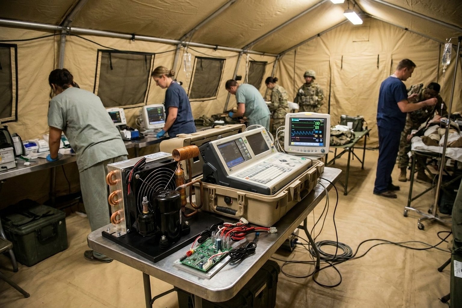
Point of care thermal management must address environmental factors that laboratory systems never encounter:
Vibration and shock: Vehicle-mounted systems experience continuous vibration (0.5-2g RMS on rough roads) and occasional shocks (5-10g during off-road transit). The BLDC rotary compressor tolerates these conditions better than reciprocating designs due to fewer moving parts and balanced rotation. Rubber isolation mounts at 4 points reduce transmitted vibration to instrument-safe levels.
Dust and particulates: Field environments expose condenser coils to dust, sand, pollen, and agricultural particulates. Washable pre-filters (replaceable every 3-6 months depending on conditions) protect the condenser from fouling. A fouled condenser reduces cooling capacity by 15-30% before triggering high-pressure protection.
Humidity and condensation: Cooling air below its dew point produces condensation on the evaporator. In tropical deployments (35°C, 85% RH), condensate production can reach 0.3-0.8 liters per hour. Drainage channels must route condensate away from sensitive electronics. In sealed instrument enclosures, a condensate collection tray with level sensor prevents overflow.
Altitude: Air density decreases with altitude, reducing condenser heat rejection efficiency. At 3,000m elevation, air density is approximately 70% of sea level. Condenser fan speed may need to increase, or a slightly oversized condenser should be specified for high-altitude deployments.
Condensate Management in Medical Environments
Condensate handling deserves special attention in point of care thermal management for medical applications. Unlike industrial enclosures where condensate simply drains to ground, medical environments impose additional constraints:
Biological contamination risk: Standing water in or near diagnostic equipment creates a potential growth medium for bacteria and mold. In medical settings, condensate must be managed as potentially contaminated fluid. Drain pans should be constructed from antimicrobial materials (copper-infused polymers or stainless steel) and designed for complete drainage with no stagnant pools.
Electrical safety in wet conditions: IEC 60601-1 requires that medical electrical equipment maintain safety even under single-fault conditions. Condensate routing must ensure that no credible leak path can direct water onto live electrical components. Physical barriers, drip shields, and gravity-directed drainage channels provide defense-in-depth against condensate-related electrical faults.
Sealed enclosure condensate cycling: In hermetically sealed instrument enclosures, moisture removed from the air during cooling accumulates in the drain pan. If the enclosure remains sealed, the total moisture content is fixed — condensate production decreases as the internal air dries. However, each time the enclosure is opened (for sample loading or maintenance), humid ambient air enters and the dehumidification cycle restarts. Sizing the drain pan for worst-case conditions (full humidity load after door opening in tropical environment) prevents overflow between maintenance intervals.
Condensate evaporation systems: For mobile applications where external drainage is impractical (portable cases, helicopter transport), a condensate evaporation tray mounted on the condenser hot side uses waste heat to evaporate collected moisture. This eliminates the need for drain hoses or manual emptying, creating a fully self-contained thermal management system suitable for any orientation or transport mode.
Regulatory Awareness
Medical devices are subject to regulatory frameworks (FDA 21 CFR, EU MDR, IEC 60601) that extend to their thermal management subsystems. Key considerations for point of care thermal management integration:
EMC compliance: The BLDC compressor driver generates switching noise that must not interfere with sensitive diagnostic measurements. Proper shielding, filtered power connections, and physical separation between the compressor electronics and measurement circuits are essential. Testing to IEC 61000-4 series standards validates electromagnetic compatibility.
Leakage current: IEC 60601-1 limits touch current and earth leakage for medical electrical equipment. The cooling system’s electrical isolation from patient-accessible surfaces must be verified during system-level safety testing.
Refrigerant safety: R134a is non-toxic and non-flammable (ASHRAE A1 safety group), making it suitable for occupied spaces including ambulance interiors. The sealed, pre-charged system eliminates field handling of refrigerant. For applications requiring lower-GWP options, the DV2820E-AC-T variant uses R290 (propane) with appropriate charge limits per IEC 60335-2-89.
Note: The cooling module itself is a component, not a finished medical device. Regulatory responsibility for the complete system rests with the device manufacturer. Thermal management specifications should be documented in the device master record (DMR) for regulatory submissions.
Application Boundaries
Point of care thermal management with micro DC air conditioning is well-suited for:
- Portable blood analyzers and chemistry panels in ambulances
- Mobile PCR and molecular diagnostics in outbreak response
- Vehicle-mounted immunoassay readers for field screening
- Reagent cold storage in mobile clinics (2-8°C maintenance)
- Portable ultrasound and imaging equipment thermal stabilization
It is not appropriate for:
- Large laboratory freezers (-20°C or below) — requires dedicated refrigeration
- MRI or CT scanner cooling — heat loads exceed micro DC capacity by orders of magnitude
- Cryogenic sample storage — requires Stirling or cascade refrigeration systems
- Cleanroom HVAC — requires filtered air handling, not spot cooling
Engineering Assessment
Point of care thermal management represents a growing engineering challenge as diagnostics move closer to patients. Compact DC vapor compression provides the only practical path to sub-ambient cooling in portable, battery-powered form factors. The technology is mature, the refrigerant is safe, and the integration patterns are well-established.
The critical design decision is matching cooling capacity to actual heat load with appropriate margin — typically 1.5-2x the calculated steady-state requirement to accommodate transient loads and degraded conditions. Under-sizing risks diagnostic accuracy; over-sizing wastes power and adds unnecessary weight.
For application-specific thermal analysis or integration support, contact our engineering team with your device heat load profile, deployment environment, and temperature requirements.
Explore Micro DC Aircon specifications for OEM integration →