
Portable Cooling Vest Power Interruption: The Cliff-Edge Problem Nobody Talks About at Rehab
You’ve been there. The scene is working — two engines, a truck company, fire mostly knocked, crews rotating through rehab. The portable cooler is humming, vest lines are circulating cold water, and the first-due crew is actually recovering. Then the generator coughs. Maybe someone plugged in the scene lights on the same circuit. Maybe the apparatus idle dipped for three seconds. Whatever the cause, the power blips — and the cooling just stops.
Not gradually. Not a slow fade. It stops like someone flipped a switch, because that’s effectively what happened. The water in the vest lines goes from actively chilled to ambient in minutes. The firefighter sitting in rehab, whose core temperature was trending down, suddenly feels a wall of heat roll back in. Experienced crew describe it as a “thermal cliff” — one moment you’re recovering, the next your body is fighting the still-warm turnout gear with zero mechanical assistance.
This article is for the equipment managers, rehab officers, and EMS supervisors who’ve watched this happen and want to understand why a portable cooling vest power interruption hits so hard — and what you can realistically do about it.
Why Power Interruption Feels Worse Than Never Cooling at All
There’s a physiological reason the cliff edge feels brutal. When active cooling is circulating cold water through a vest, the body begins vasodilation in the cooled skin zones. Blood flow to the surface increases. The cardiovascular system starts redistributing thermal load, trusting that the external cooling will continue pulling heat away.
When that cooling vanishes abruptly, the body is caught in a transitional state. Surface blood vessels are dilated, heat is being shuttled to the skin — but there’s nothing on the other side to absorb it. The subjective experience is a rapid rebound that feels hotter than baseline, even though core temperature may not have actually spiked yet. It’s the thermal equivalent of stepping out of air conditioning into a parking lot in August.
For a firefighter who just came off a working fire, this rebound isn’t just uncomfortable. It can push someone who was on the edge of heat exhaustion back into the danger zone. Rehab officers have reported (field experience, not clinical data) that crews who lose cooling mid-rehab often take 15–25 minutes longer to reach discharge vitals compared to crews who were never cooled at all. The interrupted recovery is worse than no mechanical recovery — because the body committed to a cooling pathway that got pulled out from under it.
The Root Causes of Field Power Instability
Before we talk solutions, let’s map the actual failure modes. A portable cooling vest power interruption on the fireground almost always traces back to one of these scenarios:
1. Generator Circuit Overload
This is the most common trigger. Scene generators — whether apparatus-mounted or portable — have finite capacity. A typical portable generator at a working fire is simultaneously running scene lights, fans, maybe a positive-pressure ventilation setup, and whatever else gets plugged in during the chaos of active operations. Cooling equipment gets added to the circuit, and when total draw approaches the generator’s rated output, voltage sags. When it sags enough, the cooling compressor drops offline.
Field note: The RIGID Micro Cooler draws a maximum of 18–22 amps depending on installation and environmental conditions. That’s a known, fixed parameter. The problem isn’t the cooler’s draw — it’s that nobody is tracking cumulative load on the generator circuit. A 5,000-watt generator that’s already running 3,500 watts of scene lighting doesn’t have clean headroom for a compressor startup surge, even if the steady-state math works on paper.
2. Apparatus Idle Fluctuation
Many departments run rehab cooling off the apparatus inverter rather than a standalone generator. This works — until the apparatus engine management system adjusts idle speed. Modern diesel engines with emissions controls will periodically adjust RPM for DPF regeneration, battery charging cycles, or thermal management. Each adjustment causes a momentary voltage fluctuation on the inverter output. Most lighting equipment rides through these blips without issue. Compressor-driven cooling systems are more sensitive to voltage quality.
3. Extension Cord Voltage Drop
This one is embarrassingly simple and embarrassingly common. Rehab is set up 150 feet from the apparatus. Someone grabs the longest extension cord on the rig — usually a 14-gauge, 100-foot cord — and daisy-chains a second one. By the time 12-volt DC or 120-volt AC reaches the cooler, voltage has dropped enough that the compressor can’t maintain stable operation. It runs, it stumbles, it thermal-protects, it shuts down.
Experience-based benchmark: For a draw in the 18–22 amp range, you want 10-gauge wire for any run over 50 feet. 12-gauge is acceptable up to about 50 feet. Anything thinner or longer, and you’re creating the exact instability you’re trying to avoid.
4. Shared Circuit Switching Events
Scene operations are dynamic. Someone plugs in a saw. Someone fires up a smoke ejector. Each startup event on a shared circuit creates an inrush current spike that can momentarily starve other devices on the same circuit. If your cooling system is on the same generator output as operational tools, every tool activation is a potential interruption event.
What Happens Inside the Cooler During a Power Event
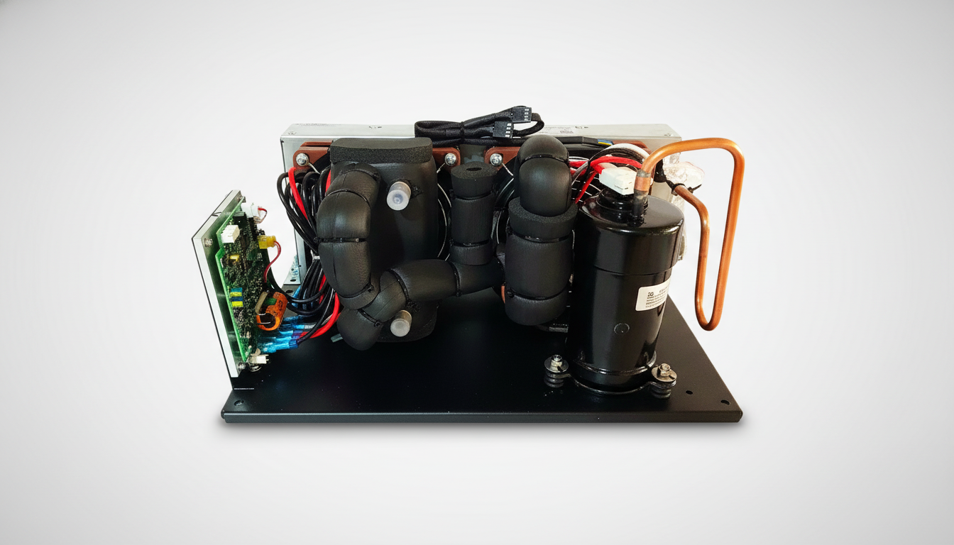
Understanding the mechanics helps explain why the cliff is so steep. A compressor-based cooling system like the RIGID Micro Cooler uses a sealed rotary micro-compressor with Freon refrigerant to chill water that circulates through the vest. When power is stable, this system can cool water to temperatures below 35°F — that’s genuine, measurable cold, not the tepid output of a melting ice bag two hours into an incident.
When power drops, the compressor stops. There’s no thermal flywheel in a vapor-compression system — the cooling output is directly coupled to compressor operation. The water in the lines retains its temperature for a short period (the thermal mass of the water itself provides a brief buffer), but without active circulation and continued chilling, that buffer depletes in roughly 2–4 minutes depending on ambient temperature and the wearer’s metabolic heat output.
This is fundamentally different from an ice-based system, where a large thermal mass (the ice) continues providing cooling passively even without power to a pump. But that comparison cuts both ways: ice systems have their own failure mode (they run out of ice and nobody notices), and they can’t reach or sustain the sub-35°F temperatures that a compressor system maintains. The tradeoff is real, and it’s why power reliability matters so much when you’re running compressor-based cooling.
The Operational Impact Nobody Puts in the After-Action Report
Here’s what makes this problem insidious: it rarely shows up as a line item in incident reviews. Nobody writes “cooling vest lost power for 90 seconds during rehab” in the AAR. Instead, the downstream effects get attributed to other causes:
- Extended rehab times — documented as “crew needed additional rest,” not as “cooling interruption extended recovery.”
- Crew refusal to use cooling — after one or two cliff-edge experiences, some firefighters opt out of vest cooling entirely. “It makes it worse when it stops” is a common complaint. They’re not wrong about the subjective experience.
- Inconsistent vital sign trends — rehab officers tracking heart rate and temperature see unexplained spikes mid-recovery. The power blip happened, the vitals responded, but the connection isn’t made because nobody logged the electrical event.
- Equipment distrust — the cooler gets labeled as “unreliable” when it’s actually the power infrastructure that failed. The equipment works exactly as designed; it just wasn’t given clean power to work with.
This last point deserves emphasis. Equipment managers who investigate cooling complaints often find nothing wrong with the cooling unit itself. The compressor runs fine on the bench. The water circulation works perfectly in the station. The problem only manifests in the field, under real-world power conditions — which is exactly where it matters most.
Practical Solutions: Building Power Resilience Into Your Rehab Setup
The fix isn’t one thing. It’s a layered approach that addresses the different failure modes mapped above.
Dedicated Circuit Allocation
The single most effective intervention is giving your cooling equipment its own circuit. This doesn’t necessarily mean a separate generator (though that’s ideal). It means:
- Identifying a dedicated outlet on the apparatus inverter that isn’t shared with scene operations equipment.
- If using a portable generator, running a separate output leg for rehab cooling — many generators have multiple outlet groups with independent breakers.
- Labeling the circuit. Physically. With tape and a marker. “REHAB COOLING — DO NOT SHARE.” In the chaos of a working fire, if it’s not labeled, it’s getting borrowed.
Right-Size Your Power Delivery
For a system drawing 18–22 amps maximum, your power infrastructure needs to accommodate both steady-state draw and startup surge:
- Generator sizing: Budget a minimum of 30-amp capacity for the cooling circuit alone. This provides headroom for compressor startup inrush (typically 1.5–2× steady-state for the first 2–3 seconds).
- Wire gauge: 10 AWG minimum for runs over 25 feet. No daisy-chaining extension cords. Period.
- Cord length: Keep the total run under 75 feet. Shorter is always better for voltage stability.
Voltage Monitoring
A simple inline voltage monitor (available for under $30) plugged into the same circuit as the cooler gives your rehab officer real-time visibility into power quality. If voltage drops below 108V (for 120V circuits), you have a problem developing before it becomes a cooling interruption. Some departments have started including a cheap plug-in voltage display as standard rehab equipment — it’s a low-cost early warning system.
Startup Sequence Protocol
If you’re running cooling and other equipment on the same generator (sometimes unavoidable), establish a startup sequence:
- Start the cooling system first, before adding other loads.
- Allow 60 seconds for the compressor to reach steady-state operation.
- Add other loads incrementally, monitoring for voltage sag.
- If voltage drops when adding a new load, that load comes off — not the cooling.
This is a cultural change as much as a technical one. It requires the department to formally prioritize rehab cooling over convenience loads like charging stations or extra lighting.
Battery-Backed Power Supply (UPS)
For departments running extended operations or working from unreliable power sources, an uninterruptible power supply (UPS) in the rehab setup provides ride-through capability during momentary generator hiccups. A UPS rated for 500–750 watts can keep a micro-compressor system running through the 3–10 second voltage dips that cause most field interruptions.
Important caveat: A UPS is a bridge, not a power source. It’s designed to smooth over brief interruptions, not run the cooling system independently for extended periods. If your generator fails completely, the UPS buys you minutes — enough to transition crew off cooling gracefully rather than hitting the thermal cliff.
Application Boundaries: When This Approach Works and When It Doesn’t
Honesty about limitations matters more than sales language. Here’s where a compressor-based portable cooling vest system excels at managing power interruption risk — and where it doesn’t:
Strong Fit
- Structure fires with established rehab: Dedicated rehab area, access to apparatus power, time to set up properly. This is the scenario where dedicated circuit allocation and proper cabling eliminate most interruption events.
- Planned events (training, planned exercises): Power infrastructure can be pre-staged and tested. Zero excuse for power instability in a planned environment.
- Fixed rehab stations (long-duration incidents): Wildland base camps, hazmat operations, extended technical rescues. These scenarios justify running dedicated generator capacity for cooling.
Challenging Fit
- Rapid deployment / first-arriving rehab: If you’re setting up cooling in the first 10 minutes of an incident with whatever power is available, electrical infrastructure is inherently unstable. Expect interruption events; plan for them rather than trying to eliminate them.
- Vehicle fires / roadside operations: Power availability is often limited to what’s on the apparatus. Circuit sharing is unavoidable. UPS bridge becomes more important in these scenarios.
- Multi-agency responses with shared power: When three departments are plugging into the same generator, circuit discipline breaks down. Mutual aid agreements should address power allocation, but they rarely do.
Not the Right Tool
- Wilderness / no-power environments: If there is no generator, inverter, or electrical power source available within cabling distance, a compressor-based system cannot operate. This isn’t a limitation of any specific product; it’s a fundamental requirement of the technology class. Battery-only operation at the 18–22 amp draw range requires significant battery infrastructure that may not be practical for field deployment.
Building a Power Reliability SOP for Rehab Cooling
Equipment managers who’ve solved this problem consistently share a common approach: they treat power for rehab cooling the same way they treat water supply for fire attack. It’s not an afterthought — it’s planned, assigned, and monitored.
A basic SOP framework:
- Pre-assign rehab power. During apparatus checks, identify and label the outlet(s) dedicated to cooling equipment. Test them monthly under load.
- Include power in rehab deployment checklist. “Cooling unit powered” is a checkbox, just like “water available” and “ALS monitoring equipment ready.”
- Train rehab officers on power monitoring. A 15-minute briefing on voltage monitoring, circuit overload signs, and the startup sequence protocol costs nothing and prevents most interruption events.
- Stock appropriate cabling. 10 AWG, 50-foot extension cords dedicated to rehab. Marked, stored with the rehab equipment, not borrowed for other uses.
- Document interruption events. When cooling drops during an incident, log it. Time, duration, probable cause. Over three incidents, you’ll see the pattern and know exactly what to fix.
The Weight-to-Reliability Equation
One reason power interruption is particularly consequential for micro-compressor cooling is the form factor advantage that makes these systems attractive in the first place. The RIGID Micro Cooler weighs less than 7 kg (15 lbs) and delivers cooling below 35°F without ice — performance that would require 20+ pounds of ice in a conventional system, ice that melts, dilutes, and loses effectiveness over a shift.
That weight advantage comes from replacing thermal mass (ice) with mechanical refrigeration (compressor). The tradeoff is direct: you gain portability and sustained cooling performance, but you become dependent on electrical power continuity. This isn’t a design flaw — it’s a physics tradeoff. The departments that get the most value from micro-compressor cooling are the ones that acknowledge and plan for this dependency rather than discovering it mid-incident.
Field-Tested Recovery Protocol After a Power Event
When an interruption does occur (and in field operations, it will eventually), having a response protocol minimizes the thermal cliff impact:
- Immediately notify affected crew. “Cooling is offline, we’re working on it.” Managing expectations reduces anxiety and the subjective perception of the thermal rebound.
- Restore power within 60 seconds if possible. The water in the vest lines retains some thermal benefit during a brief interruption. If power is restored within approximately 60 seconds, most users report the cliff effect as minimal.
- If power cannot be restored quickly, transition to passive cooling. Wet towels, shade, airflow. Don’t leave crew in a non-functioning vest — the insulating properties of the vest itself can trap heat if water isn’t circulating.
- After power is restored, allow 3–5 minutes for the system to re-chill. The compressor needs time to bring water temperature back down to effective cooling range. Don’t reconnect crew to the vest until water temperature is verified cold.
- Document and debrief. What caused the power loss? Was it preventable? Feed the answer back into your SOP.
Integration Support and Next Steps
If you’re an equipment manager evaluating how compressor-based cooling fits into your department’s rehab protocol — or if you’re experiencing power interruption events and want to troubleshoot your specific setup — the engineering team behind the RIGID Micro Cooler provides integration support for fire service and EMS applications.
This isn’t generic customer service. It’s technical consultation on power requirements, circuit design for field deployment, and compatibility with specific apparatus electrical systems. The system draws 18–22 amps maximum, weighs under 15 lbs, operates on sealed Freon with zero field maintenance, and delivers cooling below 35°F — but making those specifications work reliably in your operational environment requires understanding your specific power infrastructure.
Reach out through the product page to discuss your deployment scenario. Bring your generator specs, your typical incident profile, and your current rehab setup details. The more specific the conversation, the more useful the guidance.
Power interruption during rehab cooling is a solvable problem. It just requires treating electrical infrastructure with the same discipline you bring to every other part of the fireground operation.