
Chiller Loop Temperature Measurement: What the Sensor Choice Decides
Every sub-zero loop ends up with an argument about temperature. The chiller says −30.0 °C, the datalogger says −28.4 °C, and the sample thermocouple taped to the vessel says −26 °C. None of them is lying. They are measuring different places with different error budgets.
The Pt100 vs thermocouple question is usually presented as an accuracy contest, which it is not. Both can be right enough. What separates them is how the error behaves over time, how much of it comes from installation rather than the sensor, and what your wiring and instrument can actually read.
In chiller loop temperature measurement, installation error is usually larger than sensor error. This guide covers both, in the order that matters on a real bench.
Tolerance Classes and What They Mean Below Zero
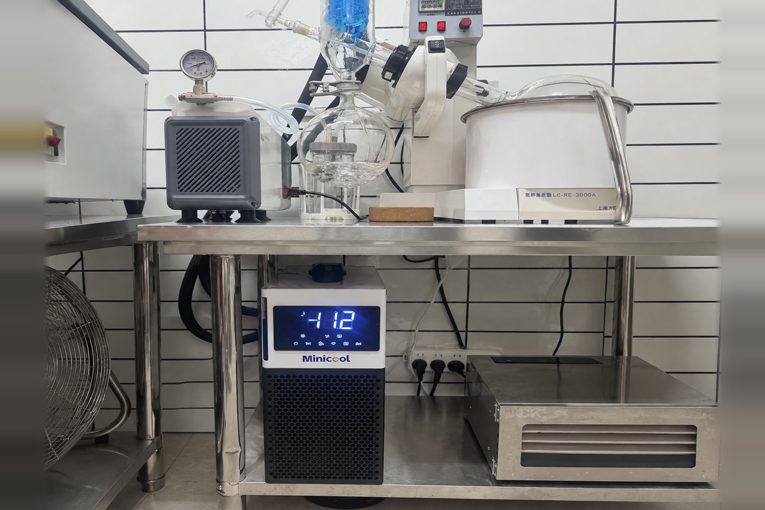 The tolerance numbers below come from the published class definitions, and they get worse as temperature moves away from 0 °C.
| Sensor | Tolerance formula | At −20 °C | At −40 °C |
|---|---|---|---|
| Pt100 Class A (IEC 60751) | ±(0.15 + 0.002 |t|) °C | ±0.19 °C | ±0.23 °C |
| Pt100 Class B (IEC 60751) | ±(0.30 + 0.005 |t|) °C | ±0.40 °C | ±0.50 °C |
| Type T thermocouple, IEC 60584-1 Class 1 | ±0.5 °C or ±0.004 |t|, whichever is greater | ±0.5 °C | ±0.5 °C |
| Type T thermocouple, IEC 60584-1 Class 2 | ±1.0 °C or ±0.0075 |t|, whichever is greater | ±1.0 °C | ±1.0 °C |
| Type K thermocouple, IEC 60584-1 Class 1 | ±1.5 °C or ±0.004 |t|, whichever is greater | ±1.5 °C | ±1.5 °C |
Quote the standard and the class together, because the same type spans a factor of two between classes and the class also has a stated temperature range that has to cover your set point. Two things follow. First, a Class 2 thermocouple’s tolerance is comparable to the temperature differences people are trying to detect in a sub-zero loop, so it is the wrong tool for proving a 0.5 K offset. Second, a Class B Pt100 is not automatically better than a good thermocouple installation, because the installation error discussed below can dwarf both figures.
Where each one earns its place
- Pt100: stable, repeatable, standard copper wiring, good linearity through the sub-zero range used by laboratory chillers.
- Thermocouple: small, fast, cheap, tolerant of abuse, easy to attach to a surface where a probe will not fit.
Installation Error: Immersion Depth and Stem Conduction
A probe reads its own sensing element, not the fluid. If the element can see the outside world through the stem, it will read partway between fluid and room.
- Immerse the sensing element at least ten stem diameters into the flow where practical, and keep the wetted length in moving fluid, not a dead leg.
- Insulate the fitting and the first stretch of stem outside the pipe. On a −30 °C line in a 22 °C room the conduction path is driving a 50 K difference.
- Prefer a thermowell in a real installation, and remember a well adds lag. Use thermal paste or a snug fit inside it.
- Surface-mounted sensors read a blend of fluid, pipe and air. Insulate over them generously and accept that the reading is indicative.
An excellent sensor installed badly is worse than a modest sensor installed correctly, because the error looks stable and therefore trustworthy.
There is a quick test for this. With the loop at a steady set point, wrap another 100 mm of insulation around the fitting and the exposed stem and watch the reading for ten minutes. If it moves, conduction was pulling the sensor toward room temperature, and it was doing so before you added the insulation. Repeat the test on a hot day and on a cold morning; a reading that shifts with the room is reporting the room as much as the fluid. This single check settles more Pt100 vs thermocouple arguments than any specification sheet, because it exposes the part of the error that the sheet never covers.
Response Time, Drift and Self-Heating
The three effects that show up after the bench has been running for a while.
| Effect | Pt100 | Thermocouple |
|---|---|---|
| Response | Slower, especially in a well; thin-film elements narrow the gap | Fast, particularly grounded junctions |
| Drift | Small and predictable if not shocked mechanically | Larger, from junction chemistry and work hardening in service |
| Self-heating | Real: excitation current warms the element, worse in still fluid | None |
| Wiring | Ordinary copper; use three- or four-wire to cancel lead resistance | Matched alloy extension all the way to the instrument |
The wiring row is where thermocouple installations quietly go wrong. A copper splice in the middle of a thermocouple run introduces a junction pair that only cancels if both sides sit at the same temperature; where they do not, the difference goes straight into the reading. In a cold room, in a cable tray, next to a warm drive, that junction moves your reading around all day.
Where the Probe Sits in a Chiller Loop
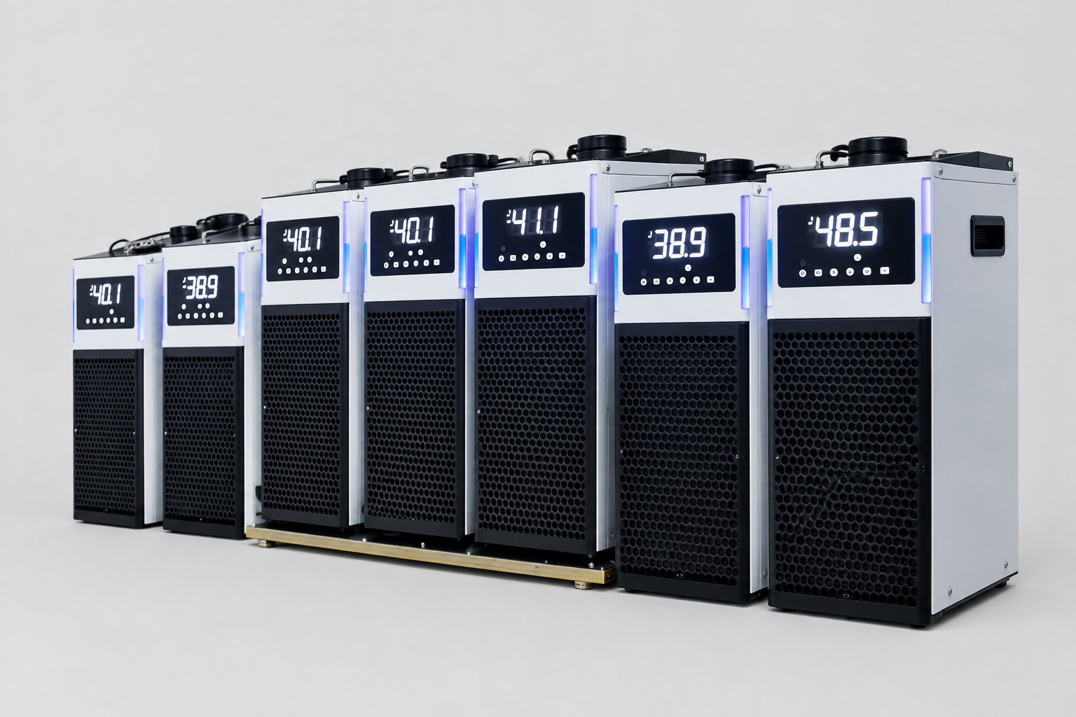 For chiller loop temperature measurement, where the probe sits decides what question you are answering.
- Chiller internal control point. The condition the machine controls and displays. Product pages do not always state where that sensor sits, so confirm it per model rather than assuming it reads the outlet.
- Chiller inlet (return). With outlet, gives the loop’s temperature rise, and therefore the load being carried.
- At the application. The number the experiment cares about. Always warmer than supply when cooling.
- In the process fluid or on the sample. The real answer, and often the hardest to instrument.
A fifth position is worth mentioning because it causes so much confusion: a probe taped to the outside of an insulated hose. It reads a mixture of fluid temperature, hose wall and whatever the insulation lets through, and it responds slowly. It is fine for spotting that a line is cold, and useless for any number that goes into a report.
Two probes, supply and return, cost little and turn a chiller into an instrument: the rise across the loop tells you the load in watts once you know flow and fluid properties. That is the same measurement used in an acceptance test checklist and in pull-down time estimation.
What the Chiller’s Own Display Tells You
RIGID’s MiniCool countertop recirculating chiller is listed with a range of 0 to −40 °C, cooling capacities of 450, 800 and 850 W, and stability of ±0.1 °C (test conditions not stated). A stability figure is not an accuracy figure: it describes how steady a reading is held, not how close that reading is to the true value, and the product page does not state where in the machine the measurement is taken.
This is also where the Pt100 vs thermocouple choice stops mattering: whatever the machine measures internally, your report needs an independent sensor whose class and calibration you control.
The product page also does not list an external process probe input, so plan any cascade or process-temperature control around equipment you have confirmed supports it. For most laboratory work the practical arrangement is simpler: let the chiller control its own supply temperature, and measure the process independently with a calibrated Pt100 and a logger.
Calibration, and the Comparison That Settles Arguments
Sensors used for chiller loop temperature measurement do not have to be laboratory-grade to be useful, but they do have to be comparable.
- Record the sensor type, class, serial number and where it is installed. An uncatalogued probe cannot be trusted six months later.
- Compare probes against each other in a stirred bath at one or two points in your working range before splitting hairs over a 0.3 K discrepancy.
- Ice point checks are a cheap sanity test for both sensor families, and they catch gross wiring errors immediately.
- Set recalibration intervals from drift history, environment and what the measurement is used for, rather than from sensor type alone; in practice thermocouples tend to need it sooner.
- Note the ambient temperature at the instrument when you calibrate. Cold junction compensation is an ambient-dependent correction, and a logger sitting in direct sun reports a different answer from the same logger in a rack.
Choosing for a Specific Job
| Task | Reasonable choice | Why |
|---|---|---|
| Proving a loop holds ±0.5 K at −30 °C | Pt100 Class A, four-wire, immersed | Sensor uncertainty must be well below the tolerance being proved |
| Mapping many points on a fixture | Thermocouples, one logger | Cheap channels matter more than absolute accuracy |
| Catching a fast transient at a nozzle | Fine thermocouple | Response time dominates |
| Long unattended runs with a report attached | Pt100 | Drift is the dominant error over weeks |
| Surface temperature on a cold plate | Either, insulated over the junction | Installation dominates; the sensor type is secondary |
A Worked Error Budget for a −30 °C Loop
The Pt100 vs thermocouple decision becomes concrete when you add the errors up. The example below assumes a supply line at −30 °C in a 22 °C room, with the goal of proving the loop holds ±0.5 K.
| Contribution | Pt100 Class A, immersed and insulated | Type T thermocouple, surface mounted |
|---|---|---|
| Sensor tolerance limit (class) | ±0.21 °C | ±1.0 °C (Class 2) |
| Instrument or logger specification | ±0.10 °C | ±0.30 °C, including cold junction compensation |
| Installation, assumed | ±0.15 °C with good immersion | ±0.80 °C on an insulated surface |
| Worst case, arithmetic sum | ±0.46 °C | ±2.10 °C |
Read the bottom row as a bound, not as an uncertainty statement. These are tolerance limits and specification limits, not standard uncertainties: a proper budget converts each one using its distribution and coverage factor, accounts for correlation, and reports an expanded uncertainty with a decision rule. Even as a bound the comparison is useful: the thermocouple chain cannot resolve a half-kelvin question, while the Pt100 chain is in the right region — but a claim that a loop meets ±0.5 K needs measured results, not this table. The installation figures are assumptions: substitute your own if you have compared probes in a stirred bath.
The same arithmetic explains why adding channels rarely helps. Twenty thermocouples give you twenty readings of comparable uncertainty, which is useful for mapping where the cold spots are, and useless for proving a half-kelvin specification.
Cost, Channels and What Laboratories Actually Do
In practice most benches end up with both, and the Pt100 vs thermocouple split follows the job rather than a preference.
- One or two Pt100s as reference instruments: supply, return, and occasionally the process itself. These are the sensors that appear in reports.
- A handful of thermocouples for mapping: fixture corners, hose surfaces, the point where frost appears, anything that needs a number rather than a measurement.
- A single logger that reads both, so timestamps line up and the comparison is meaningful.
Budget follows the same logic. A calibrated Pt100 with a four-wire input costs more than a spool of thermocouple wire, but you only need one or two of them, and they are the ones that settle disputes with a customer or an auditor.
Whatever mix you choose, write the map down: which channel is where, which class, calibrated when. Six months later the label on the cable is the only thing standing between you and repeating the whole exercise.
Common Mistakes
- Comparing the chiller display with a probe at the application and calling the difference an error, when the two are measuring different places.
- Leaving a probe stem exposed to room air and insulating only the pipe.
- Splicing thermocouple wire with copper connectors.
- Treating a stability specification as an accuracy specification.
- Settling a Pt100 vs thermocouple disagreement by trusting whichever reading looks more plausible, instead of comparing both in a stirred bath.
- Installing a probe in a dead leg where fluid does not move.
If you are specifying chiller loop temperature measurement for a sub-zero loop and want a second opinion on placement and sensor class, send us the fluid, the set point, the tolerance you have to prove and the loop layout. Ask our engineers about loop instrumentation.
Frequently Asked Questions
In a Pt100 vs thermocouple comparison, is the Pt100 always more accurate?
In the temperature range used by laboratory chillers, a Pt100 has a tighter tolerance and drifts less. But installation error usually exceeds sensor error, so a well-installed thermocouple can beat a badly installed Pt100.
Which thermocouple type suits sub-zero work?
Type T is the usual choice for sub-zero ranges, and the class matters as much as the type: IEC 60584-1 Class 1 for Type T is ±0.5 °C where Class 2 is ±1.0 °C. Type K is more often chosen for high-temperature work, and its Class 1 limit is ±1.5 °C.
How deep does the probe have to go?
Aim for at least ten stem diameters of immersion in moving fluid, and insulate the fitting outside the pipe. Shorter immersion pulls the reading toward room temperature through the stem.
Why do my two sensors disagree by 1 K?
Check placement before electronics. Different positions in the loop genuinely differ, and dead legs, poor immersion and uninsulated fittings each add their own offset. Compare the sensors side by side in a stirred bath to separate sensor error from installation error.
Can I use the chiller’s display as my measurement record?
Use it as a supply condition, not as the process record. It reports the machine’s own control point, and a stability figure quoted without test conditions does not tell you the accuracy at your set point.
Does chiller loop temperature measurement need four-wire Pt100 wiring?
Three-wire is adequate for most loop measurements; four-wire removes lead resistance entirely and is worth it for long runs or when proving tight tolerances.
References
- TC Direct, RTD Pt100 vs Thermocouple Comparison — tolerance, stability and wiring differences.
- Dwyer Omega, What’s the Difference Between Thermocouples and RTDs? — response time, drift and self-heating.