
Selecting a Recirculating Liquid Chiller Starts With Temperature, Not Capacity
Most recirculating liquid chiller selections begin with a capacity number, because capacity is the figure printed largest on every data sheet. That order is backwards. Temperature decides which class of machine is physically capable of your application, and capacity only decides which model within that class. Get the order wrong and you can specify a chiller with twice the watts you need that still cannot reach your setpoint.
The reason is that a chiller is not a heat pump with an arbitrary range. Its refrigerant, expansion device and evaporator are matched to a temperature band. Pushed below that band it loses capacity rapidly and eventually stops pulling down at all; pushed above it, the machine may not be designed to run there at all. So the sequence is: fix the setpoint, pick the machine class, then calculate the load and select the model.
This guide works that sequence in order, including a complete heat load calculation for a rotary evaporator condenser so you can see every assumption that goes into the answer.
Temperature Bands Decide the Machine Class
Before any load calculation, place your setpoint on this map. The bands are not marketing segments — they reflect what each machine class is built to do.
| Coolant setpoint | Machine class | Capacity range | Typical use |
|---|---|---|---|
| +20 °C to −20 °C | Compact liquid chiller (DV series) | 100–550 W | Laser diodes, electronics, imaging, sub-ambient process loops |
| 0 °C to −40 °C | MiniCool countertop recirculating chiller | 450–850 W | Rotary evaporation, distillation, calorimetry, analyzers |
| 0 °C to −40 °C, higher load | MidiCool | 1.3–4.6 kW | Bioreactors, material testing, chemical synthesis |
Applications below the practical range of pumped heat-transfer fluids are not simply a colder chiller — they need a different cooling architecture, such as a cold-head Stirling cryocooler, and are outside the scope of this guide.
Two boundaries in that table govern the selection:
- MiniCool and MidiCool are specified for setpoints from 0 °C down to −40 °C. Positive-temperature operation falls outside the published standard range and should be confirmed with RIGID rather than assumed from the cooling-capacity rating. For a process at +5 °C or +15 °C, the DV compact liquid chiller is the catalog answer.
- The DV series is published with a nominal −20 °C to +20 °C range (stated as ±20 °C, −4~68 °F). Applications in the 20–25 °C region sit at or above the top of that published range and need engineering confirmation rather than a catalog selection.
This is where a surprising share of selection errors originate. A laboratory buying a recirculating liquid chiller for a +10 °C jacket loop will find MiniCool’s 450 W attractive against a 550 W DV unit, and the capacity comparison looks sensible. But that setpoint is outside MiniCool’s published range, which settles the question before capacity is even considered.
The Four Heat Loads on a Recirculating Loop
Once the class is fixed, the load calculation determines the model. Heat enters a recirculating loop through four paths, and a calculation that omits any of them will come out low.
Process load
The heat the application actually generates or transfers into the coolant. For a condenser this is the latent heat of the vapor being condensed plus the sensible heat removed from the condensate. For an electronics cold plate it is the dissipated electrical power. This term normally dominates.
Ambient gain on the loop
Heat conducted into the hoses and manifolds between chiller and application. At a −20 °C setpoint in a 22 °C room the driving temperature difference is over 40 K, which makes this term far larger than most people expect, and it is the reason sub-zero loops need insulated hose while chilled-water loops often do not.
Pump work
The pump’s shaft power ends up in the fluid as heat. It is a real load on the chiller, and on small machines it is not negligible. Note that MiniCool’s pump flow, head and power draw are not published, so this term has to be treated as an allowance rather than a calculated value.
Pull-down load
The energy to bring the coolant volume and the wetted mass of the application from ambient to setpoint at startup. It does not affect steady-state sizing, but it determines how long you wait before the process can start.
Worked Example: A 5 L Rotary Evaporator Condenser
Concept lists do not select equipment, and a recirculating liquid chiller is bought against a number. Here is the complete calculation for a common case, with every assumption stated so you can substitute your own values.
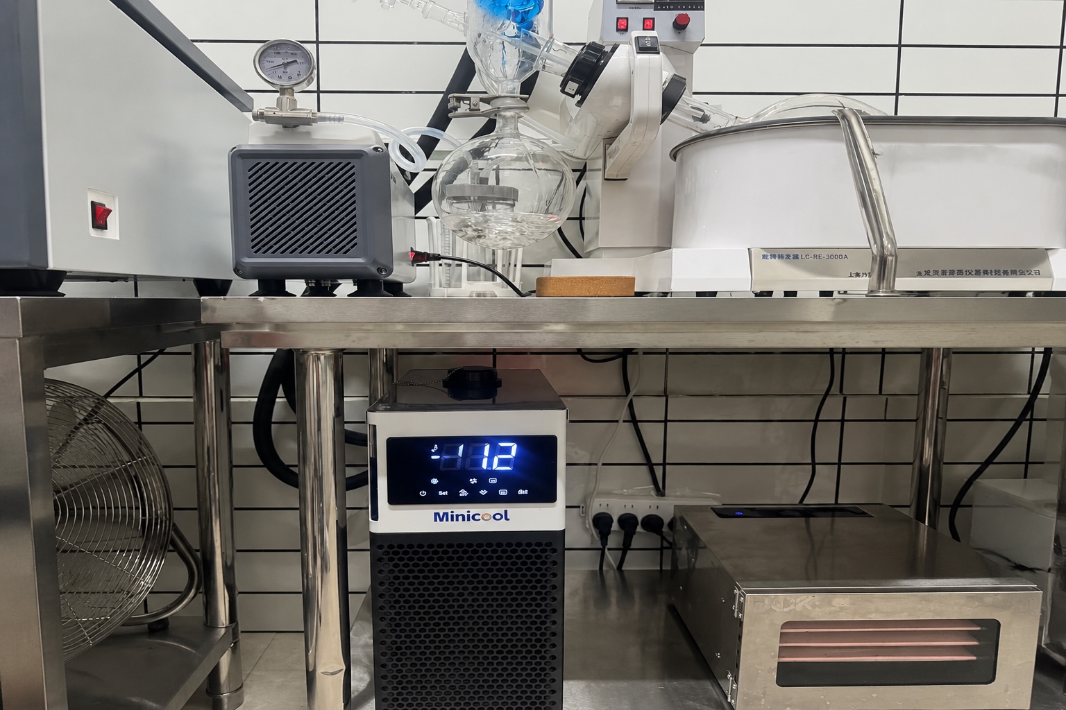 Application: 5 L rotary evaporator distilling ethanol under vacuum, coolant setpoint −10 °C, room ambient 22 °C, roughly 2 m of insulated hose each way.
Assumed inputs — these are engineering estimates, not published RIGID data:
| Input | Value used | Basis |
|---|---|---|
| Evaporation rate | 2.5 L/h | Assumed. Use your measured or expected rate — not flask volume or a pump setting |
| Ethanol density | 0.789 kg/L | Reference property, pure ethanol at 20 °C |
| Latent heat of vaporization | 841 kJ/kg | Reference property, pure ethanol at its normal boiling point |
| Liquid specific heat | 2.44 kJ/kg·K | Reference property, liquid ethanol near 20 °C |
| Vapor in / condensate out | 40 °C → 0 °C | Assumed condenser operating span |
| Insulated hose gain | 40 W allowance | Assumed for 4 m total at ~32 K difference |
| Pump heat | 30 W allowance | Assumed; pump power not published |
Two cautions before the arithmetic. The evaporation rate is the actual rate for your process, which varies with bath temperature, vacuum level, rotation speed, condenser temperature and solvent composition — it is not the flask size or a nameplate figure. And the properties below are for pure ethanol; a mixed solvent needs its own values, and the latent heat term will change with it.
Step 1 — mass flow of solvent:
2.5 L/h × 0.789 kg/L = 1.97 kg/h
Step 2 — latent load, the heat of condensing the vapor:
1.97 kg/h × 841 kJ/kg = 1,659 kJ/h ÷ 3,600 s/h = 461 W
Step 3 — sensible load, cooling the condensate from 40 °C to 0 °C:
1.97 kg/h × 2.44 kJ/kg·K × 40 K = 192 kJ/h ÷ 3,600 s/h = 53 W
Step 4 — add the loop terms:
461 + 53 + 40 (hose) + 30 (pump) = 584 W total heat load
Step 5 — apply a design margin. A 20 percent margin covers fouling, a warmer-than-design room, and the fact that the evaporation rate assumption is the least certain input:
584 W × 1.20 = 701 W required at −10 °C coolant
That number, not the box size and not the flask volume, is what you take to a selection table. On the MiniCool range it points at the 800 W or 850 W model rather than the 450 W, and it says so with a stated basis you can audit line by line. Change the evaporation rate to 1.5 L/h and the same arithmetic gives roughly 430 W, which moves the answer to the 450 W model — which is exactly why a single recommendation table indexed on flask size cannot work.
Why “701 W Required” Is Not Yet “800 W Model Selected”
One step remains before a recirculating liquid chiller can actually be ordered. The 701 W figure is a requirement at −10 °C coolant temperature, and a published capacity is a single number measured at one operating point.
For the MiniCool range the published capacities are 450 W, 800 W and 850 W, and the test conditions behind those figures are not stated on the product pages. That has a specific practical consequence: those numbers are valid for comparing the three models against each other, but they cannot be read as “800 W available at −10 °C” without confirmation.
So the correct output of this calculation is not a purchase order. It is a specific, answerable question: what is the capacity of this model at −10 °C coolant with a 22 °C ambient? A supplier that can answer that with a curve or a table is one you can design against. A supplier that repeats the headline number is one you should test before committing.
Flow Rate and Loop Design
Capacity determines whether a recirculating liquid chiller can remove the heat. Flow rate determines whether the coolant can carry it, and the two fail in different ways. An undersized loop shows up as a large temperature difference between chiller outlet and application inlet, so the process runs warmer than the setpoint even though the chiller reports that it has reached setpoint.
The governing relationship is straightforward: the heat carried equals mass flow times specific heat times the temperature rise across the application. For a fixed heat load, halving the flow doubles the temperature rise. Practical points that follow:
- Coolant choice changes the flow requirement. Below 0 °C water is not an option. A glycol or silicone-based fluid is required, and both have lower specific heat and higher viscosity than water, so the same heat load needs more flow and produces more pressure drop.
- Pressure drop rises steeply with hose length and with reduced internal diameter. Fittings, quick-connects and any internal restriction in the application all add to it.
- MiniCool’s pump flow and head figures are not published. If your loop has significant restriction or vertical rise, this is a value to request rather than assume.
Loop design is also where the stated stability specification lives or dies. MiniCool publishes ±0.1 °C stability, but that figure carries no stated test point or load condition on the product pages, and stability measured at the chiller reservoir is not the same as stability at the process. A loop with marginal flow will show good reservoir stability and poor process stability at the same time.
Matching to the MiniCool Range
With a required capacity and a confirmed operating point, recirculating liquid chiller selection is a lookup.
| Model | Published capacity | Temperature range | Stability | Dimensions | Weight | Noise |
|---|---|---|---|---|---|---|
| MiniCool 450 | 450 W | 0 °C to −40 °C | ±0.1 °C (test point not stated) | 200 × 430 × 450 mm | 18–25 kg | <45 dB |
| MiniCool 800 | 800 W | 0 °C to −40 °C | ±0.1 °C (test point not stated) | 200 × 430 × 450 mm | 18–25 kg | <45 dB |
| MiniCool 850 | 850 W | 0 °C to −40 °C | ±0.1 °C (test point not stated) | 200 × 430 × 450 mm | 18–25 kg | <45 dB |
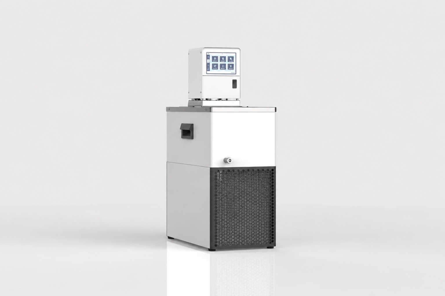 The three models share an enclosure, so a capacity upgrade does not cost bench space — a useful property when the load estimate is uncertain and the margin between 450 W and 800 W is the difference between adequate and comfortable. Refrigerant options across the series include R134a, R290 and R1234yf, and supply can be AC (120–240 V) or DC. Full model data is on the MiniCool product page.
Where the setpoint is above 0 °C, the selection moves to a different family entirely — the DV compact liquid chiller covers 100–550 W between +20 °C and −20 °C. The two ranges overlap between 0 °C and −20 °C, and in that overlap the decision is made on capacity, footprint and supply voltage rather than on temperature.
Where Selection Goes Wrong
Sizing from the instrument instead of the load
“A 5 L rotovap needs an X watt chiller” is not a valid rule, because the same instrument produces very different loads depending on solvent, vacuum level and evaporation rate. The worked example above changes by a factor of nearly two on evaporation rate alone.
Ignoring ambient gain on sub-zero loops
Running uninsulated hose on a −20 °C or −40 °C loop. The temperature difference to the room is larger than the difference across many process heat exchangers, and the gain shows up as a chiller that runs continuously without reaching setpoint.
Using water below 0 °C
Obvious when stated, common in practice during commissioning. Below 0 °C a suitable heat transfer fluid is required, and its lower specific heat has to be carried through the flow calculation rather than assumed away.
Specifying stability without a test point
Writing ±0.1 °C into a specification without defining where and under what load it is measured. Stability at the reservoir under no load is a different quantity from stability at the process under full load.
The Selection Sequence
- Fix the coolant setpoint and the room ambient.
- Place the setpoint on the temperature band table to identify the machine class. Above 0 °C falls outside MiniCool’s published standard range.
- Calculate the process load from first principles for your application.
- Add ambient gain on the loop, sized from hose length, insulation and the temperature difference to the room.
- Add a pump heat allowance.
- Apply a design margin — 20 percent is a reasonable starting point when the process load estimate is uncertain.
- Confirm the candidate model’s capacity at your setpoint, not at the headline condition.
- Check flow rate against the temperature rise your process can tolerate, using the specific heat of the actual coolant.
- Verify pull-down time meets your workflow.
Steps 2 and 7 are the ones that most often get skipped, and the ones that produce failures you cannot fix after delivery. A cost comparison against consumable cooling methods is covered in our analysis of recirculating chillers versus dry ice and ice baths, and the countertop form factor trade-offs are covered in our small recirculating chiller buying guide.
If you would rather have the operating point confirmed than interpolated, send the following and our engineers will return a model recommendation with the capacity at your condition: coolant setpoint, maximum room ambient, process heat load or the instrument and solvent, required flow rate or acceptable temperature rise, coolant fluid, hose length and internal diameter, supply voltage, required pull-down time, available bench or floor space, and whether this is a prototype or a production quantity. Send your operating conditions to our engineering team.
Frequently Asked Questions
How do I calculate the chiller size for a rotary evaporator?
Multiply the solvent evaporation rate by its latent heat of vaporization to get the dominant term, add the sensible heat of cooling the condensate, add allowances for ambient gain on the hoses and for pump heat, then apply a design margin. For a 5 L rotovap on ethanol at 2.5 L/h the worked example above gives roughly 584 W of load and about 700 W of required capacity at −10 °C. At 1.5 L/h the same method gives roughly 430 W. The evaporation rate is the input that moves the answer most, so estimate it for your own process rather than borrowing a figure.
Can a recirculating liquid chiller run above 0 °C?
It depends on the machine class, and this is the single most common selection error. MiniCool and MidiCool are sub-zero machines with an upper limit of 0 °C and should not be specified for positive-temperature work. For setpoints between 0 °C and +20 °C the DV compact liquid chiller is the correct family. Applications above +20 °C sit at or beyond that ceiling and need engineering confirmation.
What coolant should I use below 0 °C?
Water is not usable below 0 °C. A glycol solution or a silicone-based heat transfer fluid is required, chosen so that its freezing point sits comfortably below your lowest setpoint. Both have lower specific heat and higher viscosity than water, so the flow rate needed to carry a given heat load is higher and the loop pressure drop is greater. Carry the actual fluid properties through the flow calculation rather than sizing on water and substituting later.
Why does my chiller reach setpoint but my process stays warm?
Insufficient flow is one common cause, but not the only one. The chiller controls on its own reservoir temperature, so it can report setpoint reached while the process stays warm for several different reasons: inadequate flow, hose diameter or a restriction; insufficient heat-exchanger area or high contact thermal resistance at the load; bypass flow that never reaches the application; fouling; coolant properties unsuited to the duty; sensor placement or calibration offset between the chiller and the process; or simply that the reservoir has reached setpoint while the load has not yet reached steady state. Start by measuring the temperature difference between chiller outlet and process inlet, and across the application itself — that pair separates a loop problem from a heat-exchanger problem.
What does ±0.1 °C stability actually mean?
The test point and load condition behind that figure are not stated on the MiniCool product pages. It is a control specification whose value depends entirely on where and under what load it is measured, so treat it as an indication of control-loop quality rather than as a guaranteed value at your process. If temperature stability is critical to your measurement, define the test point in your specification and ask for data at that point.
How long should pull-down take?
Pull-down time depends on the coolant volume in the chiller and loop, the wetted thermal mass of the application, the starting and target temperatures, and the capacity available across that span. It is not a steady-state sizing input, but it does determine workflow, and a chiller sized tightly for steady-state load will pull down slowly. If start-up time matters, state it as a requirement rather than discovering it after installation.