
Refrigerated Centrifuge Cooling: the Rotor Is the Load, Not the Sample
A centrifuge holding samples at 4 °C looks like a small cooling problem. A few hundred milliliters of liquid, a modest temperature difference, an insulated chamber — the arithmetic suggests tens of watts.
The arithmetic is answering the wrong question. Once a rotor is spinning, the dominant heat source is not the sample and not the room. It is the rotor itself, churning the air in the chamber, and windage heating rises steeply with speed rather than proportionally. A machine that holds 4 °C comfortably at moderate speed can drift several degrees at high speed with the same samples in it.
Refrigerated centrifuge cooling therefore has to be specified against the speed the instrument actually runs at, and this guide covers where that load comes from, when an external chiller helps, and what to do when the built-in system is the constraint.
Where the Heat Comes From
| Source | Behavior | Relative weight at high speed |
|---|---|---|
| Rotor windage | Rises steeply with rotational speed | Dominant |
| Motor and drive losses | Rises with load and speed | Significant |
| Chamber heat gain | Steady, set by insulation and room temperature | Modest |
| Sample pull-down | One-time, at the start of a run | Transient |
| Bearing friction | Rises with speed | Small but not zero |
Two features of that table shape refrigerated centrifuge cooling decisions downstream. The largest term depends on a variable the cooling system cannot influence, and it is the variable the user changes between runs. And the term most people size against — the sample — is a transient that disappears once the contents reach temperature.
This is why a centrifuge specification quoted as “maintains 4 °C” is incomplete without the speed it was measured at, and why the same instrument behaves differently in the hands of two users running different protocols.
Why Windage Is Not Linear
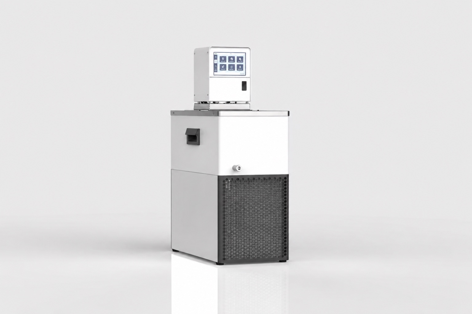 The steep part of refrigerated centrifuge cooling is aerodynamic. Drag on a rotating body scales with the square of velocity, and the power dissipated scales with velocity cubed. The practical consequence for refrigerated centrifuge cooling is stark: doubling the speed can raise the windage load by roughly a factor of eight.
Three implications follow:
- Headroom that looks generous at moderate speed can disappear entirely at the top of the range. A design margin evaluated at 8,000 rpm says very little about behavior at 16,000 rpm.
- Rotor geometry matters as much as speed. A larger diameter rotor, or one with more exposed surface, dissipates more at the same rotational speed.
- Chamber pressure matters, which is why high-speed instruments evacuate the chamber. Removing the air removes the medium windage acts on, and it is the only way to make very high speeds thermally practical.
The cube relationship also explains something users notice and rarely connect: a protocol run at 90 percent of maximum speed rather than 100 percent reduces the windage load by roughly a quarter. Where a run is thermally marginal, a small reduction in speed buys a disproportionate amount of thermal headroom, and it is often available at no cost to the separation.
For instruments without a vacuum system, the cooling requirement at maximum speed is simply large, and it is the number the refrigeration has to be specified against.
When an External Chiller Earns Its Place
Most instruments have built-in refrigeration, so the refrigerated centrifuge cooling question is not whether cooling is needed but whether the built-in system is sufficient. Four situations point at external cooling.
The built-in system rejects into the room
A centrifuge with an air-cooled condenser dumps everything — windage, motor losses and sample heat — into the laboratory. In a small or already-warm room that raises ambient, which raises condensing temperature, which reduces the machine’s own capacity. The instrument and the room work against each other, and the effect is worst in exactly the conditions where performance matters.
Long runs at high speed
A machine that holds temperature during a twenty-minute run may drift during a four-hour one, because the chamber and rotor mass have reached equilibrium with a load the refrigeration cannot fully remove. The symptom is a temperature that is correct at the start and wrong at the end.
Rotor pre-cooling
A room-temperature rotor is a substantial thermal mass, and it warms the samples before the refrigeration catches up. Pre-cooling the rotor separately removes that transient from the run entirely, and a small circulating bath is a common way to do it.
Removing heat from a temperature-controlled room
In a laboratory whose own air conditioning is the constraint, every watt the centrifuge rejects is a watt the room system has to remove again. Moving that rejection to a liquid loop that discharges elsewhere takes the load off the room entirely, which can be worth more than the improvement to the instrument itself. This is the same argument that applies to any sealed-loop retrofit, and it is usually the one that justifies the cost.
Retrofitting temperature control
Where a non-refrigerated instrument needs temperature control added, an external loop to a jacketed chamber or a cooled plate is the practical route.
Sizing an External Loop
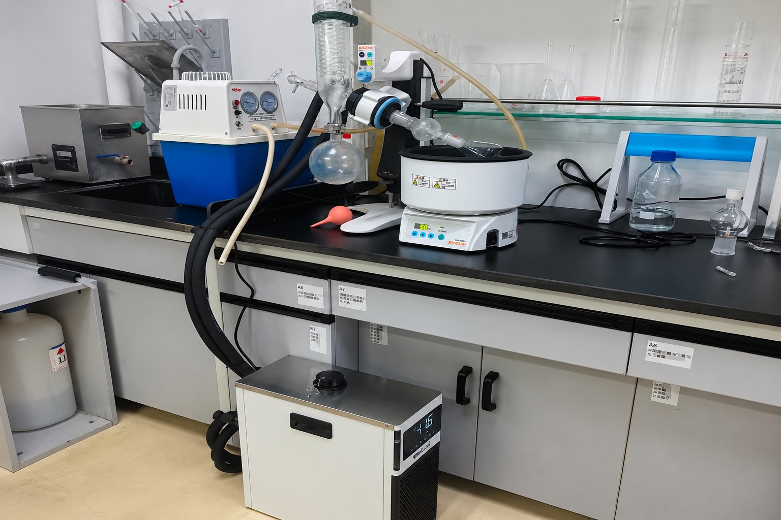 Sizing an external loop for refrigerated centrifuge cooling has to start from the load at the operating condition, not at a nominal one.
| Input | Value used | Basis |
|---|---|---|
| Windage and motor losses at operating speed | 250 W | Assumed; establish by measurement for the actual rotor and speed |
| Chamber heat gain | 40 W | Assumed at a 4 °C chamber in a 22 °C room |
| Hose and heat exchanger losses | 35 W | Assumed for an insulated sub-ambient loop |
| Pump heat | 30 W | Assumed; pump power not published |
| Design margin | 20 % | Assumed practice |
Steady load: 250 + 40 + 35 + 30 = 355 W. With margin: 426 W at the sink temperature.
The first row carries all the uncertainty, and it is the row worth measuring rather than assuming. A practical method requires no instrumentation beyond a thermometer: run the instrument at the target speed with the refrigeration disabled and a known thermal mass in the chamber, and observe the rate of temperature rise. Multiply by the thermal capacity and the windage plus motor load falls out directly.
Two cautions on that method. The thermal mass has to include the rotor, which usually dominates whatever else is in the chamber, and the observation window has to be short enough that the chamber has not warmed far from its target — because both windage and chamber gain change as temperature rises. Take the slope early in the rise rather than averaging over a long one.
That measurement takes one afternoon and replaces the single largest guess in the calculation.
Setpoint and Temperature Zone
Refrigerated centrifuge cooling targets a chamber temperature, but the equipment specification is set by the sink temperature the loop has to hold — and those are different numbers separated by the heat exchanger and the loop losses.
Most chamber targets in this work sit above freezing, and the sink has to sit below the chamber by enough to drive the heat transfer. How far below decides which machine family applies.
- Where the sink itself remains above 0 °C, or sits in the mildly negative region, the DV compact liquid chiller family is the applicable range: 100–550 W across a published −20 °C to +20 °C span, covering the whole band a positive-temperature chamber normally needs.
- Where the sink has to be genuinely sub-zero — for rapid rotor pre-cooling, or for a chamber below freezing — the requirement moves to the MiniCool range, published at 450 W to 850 W across 0 °C to −40 °C. Model data is on the MiniCool product page.
- That boundary is a specification, not a preference. MiniCool is published for setpoints from 0 °C down to −40 °C; sink temperatures above 0 °C fall outside its published standard range and should be confirmed with RIGID rather than assumed from the capacity figure.
Once the sink is below freezing the coolant becomes a glycol or silicone fluid rather than water, which brings the viscosity, flow and condensation consequences that apply to any sub-zero loop — and those consequences appear at the heat exchanger, which is where refrigerated centrifuge cooling is least tolerant of reduced flow.
What Goes Wrong
- Sizing on sample mass. The sample is a transient; windage is the steady load, and at high speed it is an order of magnitude larger.
- Sizing at a nominal speed rather than the maximum used. Because windage rises so steeply, a margin evaluated low in the range is not a margin at the top.
- Ignoring the room. A machine rejecting into a small laboratory raises its own condensing temperature and reduces its own capacity.
- Skipping rotor pre-cooling and then blaming the refrigeration for a slow start. That transient is avoidable rather than a capacity problem.
- Sizing the loop from the chamber temperature rather than the sink temperature. The two differ by whatever the heat exchanger and the loop losses impose, and it is the sink figure that the machine has to deliver.
- Assuming a temperature specification applies at all speeds. It applies at the condition it was measured at, and the instrument’s own documentation is where that condition should be found.
Instrument-specific cooling requirements across analytical equipment are covered in our guide to chillers for analytical instruments, and sizing against peaks rather than averages in our discussion of peak load sizing.
If you want an external loop sized, send the following and our engineers will advise: instrument model and rotor type, maximum operating speed and typical run duration, target chamber temperature, whether the chamber is evacuated, measured or estimated windage load if available, room temperature, and whether rotor pre-cooling is required. Send your instrument details to our engineering team.
Frequently Asked Questions
Why does my centrifuge run warm only at high speed?
Windage. Aerodynamic power dissipation scales roughly with the cube of rotational speed, so doubling the speed can raise the heat load by around a factor of eight. Refrigerated centrifuge cooling that is comfortable at moderate speed can be entirely consumed at the top of the range with the same samples loaded. The specification applies at the speed it was measured at.
Is the sample the main cooling load?
Only at the start of a run, while the contents are being brought to temperature. Once they are there, the sample contributes almost nothing and the steady load is rotor windage plus motor and drive losses. Sizing against sample mass is the commonest error in this application and it understates the requirement substantially.
How do I measure the actual load?
Run the instrument at the target speed with refrigeration disabled and a known thermal mass in the chamber, and record the rate of temperature rise. Multiply the rate by the thermal capacity of that mass and the windage plus motor load falls out directly. It requires only a thermometer and it replaces the largest assumption in the sizing calculation.
Would an external chiller help my existing centrifuge?
It depends which constraint you have. If the machine drifts during long high-speed runs, or if it is rejecting heat into a small warm room and reducing its own capacity, external cooling addresses a real limit. If the problem is a slow start from a room-temperature rotor, pre-cooling the rotor is cheaper and solves it completely.
Should the sink be sub-zero?
Only if the chamber target or the pull-down rate requires it. A +4 °C chamber with a sink around −10 °C sits inside the published range of a positive-temperature compact liquid chiller. A colder sink speeds pull-down and suits chambers below freezing, and moves the selection to a sub-zero machine — with the coolant, viscosity and condensation consequences that follow.
Why do high-speed centrifuges evacuate the chamber?
Because windage acts on the air in the chamber, so removing the air removes the load. At the speeds ultracentrifuges reach, the windage heating in atmospheric air would be impractical to remove by refrigeration at any reasonable capacity. Evacuating the chamber is not primarily about drag on the rotor — it is about not having to cool the heat that drag would produce.