
Rethinking Sealed Enclosure Cooling Maintenance: Beyond the Filter
For engineers and maintenance managers overseeing industrial automation, telecom infrastructure, or outdoor kiosks, the routine of managing enclosure cooling can feel like a never-ending cycle. The most common culprit? The humble air filter. It’s a component designed to protect sensitive electronics, but it often becomes the primary point of failure, demanding constant cleaning, replacement, and operational downtime. This cycle represents a significant, and often underestimated, operational expenditure (OpEx).
The conventional approach of using fans and filters creates an open-loop system that inevitably draws in the very contaminants you’re trying to block. In harsh environments, a filter can become clogged in weeks, or even days, compromising the entire thermal management strategy. This leads to a cascade of problems, from component derating to catastrophic system failure. The solution lies in shifting the engineering paradigm from filtering ambient air to isolating the internal environment completely. This is the principle behind modern, closed-loop DC air conditioning.
By the end of this article, you will have a comprehensive understanding of the engineering principles that enable filterless enclosure cooling. We will explore the failure modes of traditional systems, detail the mechanics of closed-loop vapor-compression cooling, and provide a practical framework for selecting and implementing a solution that drastically reduces the burden of sealed enclosure cooling maintenance and improves system reliability.
Context: Where Traditional Cooling Maintenance Costs Escalate
The hidden costs of filter-based cooling become apparent in environments where the air is anything but clean. Two common scenarios highlight the operational challenges and financial drain associated with constant maintenance.
Scenario 1: The Industrial Automation Floor
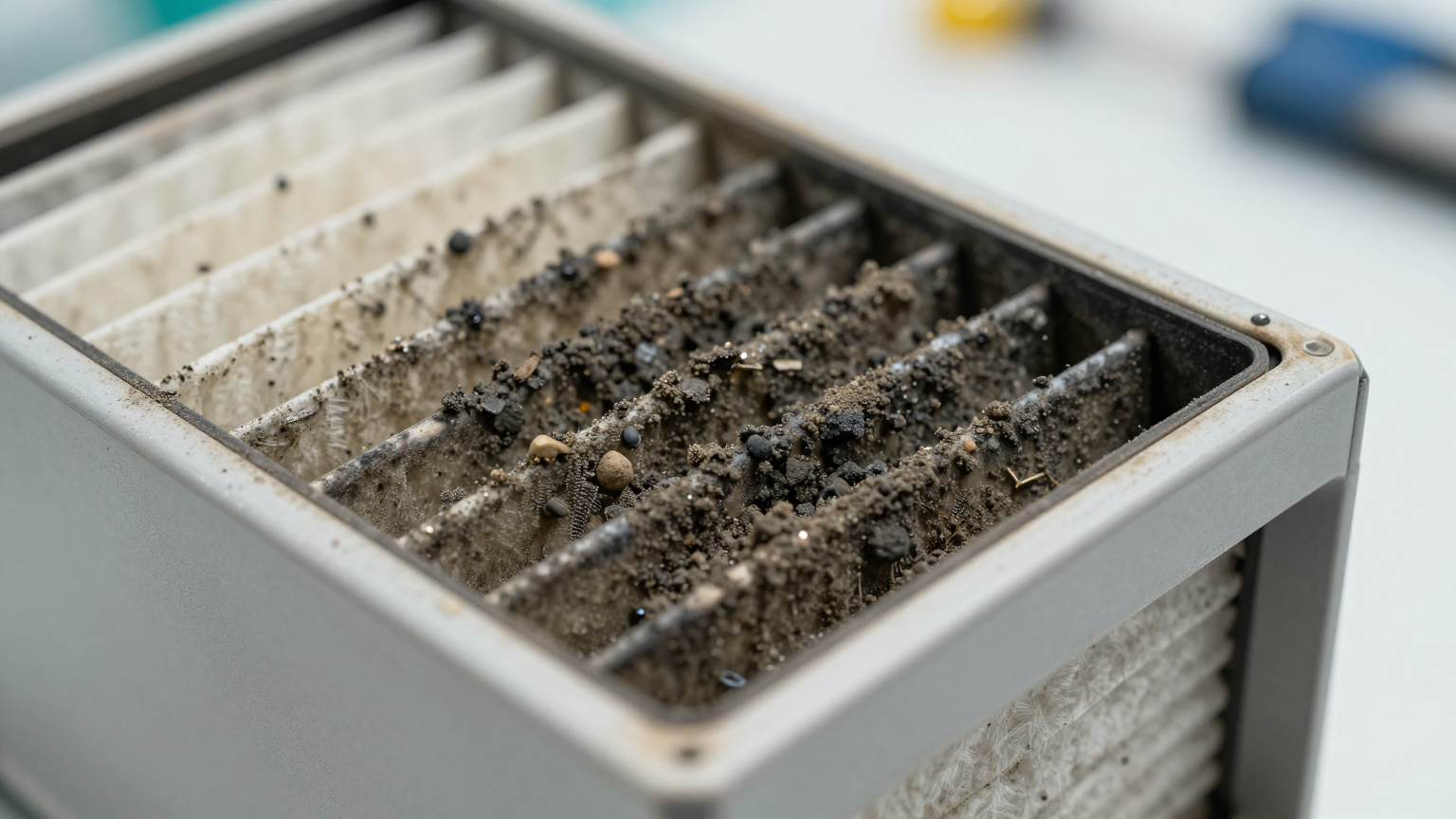
Consider a busy CNC machining facility. The air is thick with a mixture of fine metal shavings, coolant mist, and hydraulic oil vapor. Control cabinets for robotic arms, PLCs, and VFDs are mission-critical, yet they are constantly under assault. An open-loop system with a fan and filter will pull this contaminated air directly towards the electronics it’s meant to protect. The filter quickly becomes saturated with a sticky, obstructive paste. Maintenance teams are forced into a reactive cycle: either they adhere to a costly, high-frequency cleaning schedule, or they risk thermal alarms and production halts when a clogged filter causes a drive to overheat. Each maintenance action requires a technician, production downtime, and replacement parts, accumulating significant costs over the equipment’s lifespan.
Scenario 2: Remote and Outdoor Deployments
In the telecommunications and edge computing sectors, equipment is often housed in outdoor cabinets located in dusty, humid, or saline environments. These sites—from desert cell towers to coastal utility nodes—are typically unmanned. A simple clogged filter can go unnoticed for months, silently degrading the performance and lifespan of sensitive radio equipment or servers. When the system finally fails due to overheating, the cost is not just in the replacement hardware but also in the expensive truck roll required to dispatch a specialized technician to a remote location. For these applications, a system that requires minimal human intervention isn’t a luxury; it’s a core design requirement. This is where solutions like those for telecom components cooling become critical.
Common Failure Modes of Filter-Based Cooling Systems
The reliance on filtration as the primary defense mechanism in open-loop cooling systems introduces several predictable points of failure. Understanding these vulnerabilities is the first step toward designing a more robust thermal management strategy.
- Progressive Filter Clogging (Fouling): This is the most common failure mode. Dust, dirt, oil, and moisture accumulate on the filter media, steadily increasing its resistance to airflow. As airflow diminishes, the fan’s ability to remove heat from the enclosure plummets, even if the fan itself is operating at full speed.
- Component Derating and Thermal Runaway: As internal temperatures rise due to poor airflow, sensitive electronics like processors, power supplies, and variable frequency drives begin to derate—their performance is automatically throttled to prevent heat damage. If the temperature continues to climb, it can lead to a complete shutdown or permanent hardware failure.
- Humidity and Condensation Ingress: In humid locations, an open-loop system continuously draws in moist ambient air. If the internal enclosure surfaces are cooler than the dew point of this air, condensation will form. This moisture can lead to short circuits, corrosion on PCB traces, and premature failure of connectors and components.
- Compromised Enclosure Sealing: NEMA and IP ratings are crucial for protecting electronics from dust and water. Every time a technician opens an enclosure door to service a filter, the integrity of the door gasket is tested. Over time, repeated access can lead to worn seals, loose latches, and a compromised enclosure, rendering the rating ineffective.
- Increased Energy Consumption: A clogged filter forces the cooling fan to work harder to try and pull air through the restrictive media. This increased effort results in higher energy consumption for progressively less effective cooling, reducing the system’s overall efficiency.
- High Total Cost of Ownership (TCO): The initial cost of a fan and filter system is low, but the TCO is often deceptively high. When you factor in the recurring costs of replacement filters, the labor hours for maintenance, the energy waste, and the financial impact of equipment downtime, the long-term expense can far exceed that of a more advanced, sealed cooling solution.

Engineering Fundamentals: The Closed-Loop Advantage
The solution to the problems plaguing open-loop systems is to create a sealed, closed-loop environment. This design fundamentally separates the internal cabinet air from the external ambient air, enabling a true filterless enclosure cooling architecture.
Closed-Loop vs. Open-Loop Air Circulation
Think of the difference between opening a window on a hot day versus turning on an air conditioner. Opening a window (open-loop) lets in cool air, but it also brings in dust, pollen, humidity, and noise. An air conditioner (closed-loop) recirculates and cools the air already inside the room, keeping the outside environment separate. A sealed enclosure cooler operates on the same principle. It creates two distinct airflow paths:
- The Internal Loop: A fan circulates air within the sealed enclosure. This air passes over a cold evaporator coil, where heat from the electronics is absorbed into a refrigerant. The cool, dehumidified air is then directed back over the components.
- The External Loop: The refrigerant carries the absorbed heat to a condenser coil located on the outside of the unit. An external fan blows ambient air over the condenser, dissipating the heat into the surrounding environment.
Crucially, the internal and external air streams never mix. This isolation is what eliminates the need for a filter on the internal loop, as no outside contaminants can enter the enclosure. The only maintenance required is occasional inspection of the external condenser coils, which are designed to handle environmental exposure.
Active Heat and Humidity Removal
Unlike a simple fan, a closed-loop system based on vapor-compression technology, such as a Micro DC Aircon, actively removes heat rather than just moving it around. This process also inherently dehumidifies the air. As the warm, moist internal air passes over the cold evaporator coil, its temperature drops below the dew point, causing water vapor to condense out of the air. This condensate is collected and typically drained or evaporated outside the enclosure. By maintaining a low internal dew point, the system prevents condensation from forming on sensitive electronics, a critical advantage in humid or coastal environments.
Key Specifications for Sealed Cooling Systems
When evaluating a sealed cooling solution, certain specifications are paramount for ensuring performance and reliability. While specific values vary by model, understanding the parameters of a product series provides a strong baseline for selection.
The Rigid Chill Micro DC Aircon series, for example, is built around a vapor-compression system using a BLDC inverter rotary compressor. This technology is key to achieving high efficiency and precise temperature control. Below are the typical specifications and why they matter:
| Parameter | Typical Specification | Engineering Significance |
|---|---|---|
| Cooling Capacity Range | 100W – 900W | Must be correctly sized to the enclosure’s total heat load (internal components + solar gain). Undersizing leads to overheating; oversizing leads to inefficient short-cycling and reduced equipment life. |
| DC Voltage Options | 12V / 24V / 48V | Allows for direct integration with battery banks, vehicle power systems, or standard DC power supplies found in telecom and industrial settings, eliminating the need for inefficient AC-DC inverters. |
| Refrigerant Options | R134a / R290 / R1234yf | Provides flexibility to meet different regional environmental regulations (e.g., F-Gas) and application-specific performance requirements. |
| Control System | Integrated PCB with variable-speed control | A variable-speed (inverter) compressor and fans can match cooling output to the real-time heat load. This is far more efficient than simple on/off systems and reduces mechanical stress, extending the unit’s service life. |
A 4-Step Framework for Selecting a Low-Maintenance Solution
Transitioning to a sealed, low-maintenance cooling system requires a systematic approach. Following this four-step process will help ensure you select a solution that is both effective and reliable for your specific application.
Step 1: Define Your Thermal and Environmental Inputs
The first step is to gather data. You cannot specify a cooling system without knowing the challenge it must overcome. Quantify the following:
- Internal Heat Load: Calculate the total heat dissipated by all components inside the enclosure (in watts). This is the primary heat load the system must remove.
- Maximum Ambient Temperature: Determine the highest expected external temperature the enclosure will experience. This defines the “hot side” temperature for the heat exchanger.
- Target Internal Temperature: Specify the maximum allowable temperature inside the enclosure to ensure all electronics operate safely and reliably.
- Environmental Conditions: Identify the types of contaminants present (e.g., dust, oil, moisture, corrosive agents) and any exposure to direct sunlight (solar load), which adds significant heat.
Step 2: Identify System Constraints and Requirements
Next, define the physical and electrical boundaries of the project:
- Enclosure Integrity: What is the required NEMA or IP rating for the enclosure? The cooling unit must be able to mount to the enclosure without compromising this seal.
- Available Power: What DC voltage is available (12V, 24V, 48V)? Is the power supply stable and capable of handling the compressor’s startup current?
- Physical Space: What are the dimensional constraints for mounting the cooling unit (e.g., side, door, or top mounting)?
- Control and Alarms: Do you need remote monitoring, alarm outputs for high temperature, or variable speed control based on an internal sensor?
Step 3: Size the Cooling Unit Correctly
With the data from Step 1 and 2, you can perform a thermal calculation to determine the required cooling capacity. It is critical to account for all heat sources, not just the internal electronics. A common mistake is to ignore the solar load on outdoor cabinets, which can add hundreds of watts to the total heat load. Always size for the worst-case scenario. It is highly recommended to consult with a thermal management specialist during this phase. An undersized unit will fail to protect your equipment, while a grossly oversized unit will be inefficient and costly.
Step 4: Validate the Closed-Loop Design
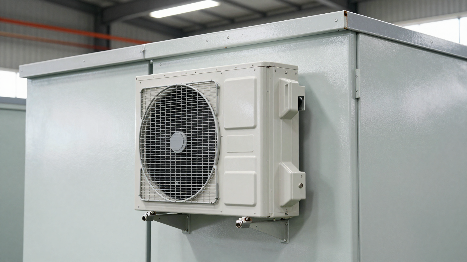
Finally, confirm that your chosen solution provides a true closed-loop system. The unit must have separate, gasket-sealed airflow paths for the internal (evaporator) and external (condenser) sides. This is the cornerstone of effective sealed enclosure cooling maintenance. A properly designed unit will maintain the enclosure’s NEMA or IP rating and ensure that no ambient air can contaminate the protected internal environment.
Implementation Checklist for Maximum Reliability
Proper installation is just as critical as proper selection. A poorly installed unit can compromise the seal and negate the benefits of a closed-loop design. Follow this checklist to ensure a robust and reliable implementation.

- Mechanical Integration
- Verify Enclosure Seal: Before installation, confirm that the enclosure itself is properly sealed. Check all door gaskets, cable glands, and conduit entries. A sealed cooling unit cannot protect a leaky box.
- Prepare Mounting Surface: Ensure the mounting surface is clean, flat, and structurally sound. Follow the manufacturer’s template for cutting the mounting holes precisely.
- Use All Gaskets: Carefully install all gaskets provided with the cooling unit. These are essential for maintaining the seal between the unit and the enclosure, and between the internal and external air paths. Torque mounting bolts to the specified values to ensure even compression.
- Electrical Integration
- Use Correct Wire Gauge: Select wiring that is appropriately sized for the unit’s maximum current draw at the specified DC voltage to prevent voltage drop.
- Ensure Power Quality: Connect the unit to a stable, regulated DC power supply. Unstable power can damage the sensitive control electronics (PCB) and compressor driver.
- Connect Control Signals: If using remote control, alarm outputs, or temperature sensors, ensure they are wired according to the schematic to enable proper system monitoring and functionality.
- Thermal Commissioning
- Perform a System Test: After installation, power on the system and allow it to run under a normal or simulated heat load.
- Monitor Temperatures: Place temperature sensors inside the enclosure to verify that the internal air temperature is being maintained at or below your target setpoint.
- Check Condensate Management: For units with active dehumidification, verify that condensate is being properly collected and drained or evaporated away from the enclosure.
- Long-Term Maintenance Plan
- Schedule External Coil Inspection: While the internal loop is filterless, the external condenser coils can still accumulate debris over time. Schedule periodic inspections (e.g., semi-annually or annually, depending on the environment) and clean the coils with compressed air or a soft brush if necessary.
- Check Fan Operation: During inspections, listen for any unusual noise or vibration from the fans, which could indicate a pending bearing failure.
Frequently Asked Questions (FAQ)
- 1. Is “filterless” truly maintenance-free?
- It is more accurately described as “low-maintenance.” While there are no internal filters to clean or replace, the external condenser coils that dissipate heat to the ambient environment may require occasional cleaning, especially in very dusty or dirty locations. However, this maintenance interval is drastically longer than for traditional filters.
- 2. How does a sealed system handle humidity that is already inside the enclosure?
- A key function of a closed-loop air conditioner is dehumidification. As it cools the internal air, moisture condenses on the cold evaporator coil and is removed from circulation. This actively reduces the internal relative humidity, protecting components from moisture damage.
- 3. What if my heat load varies significantly?
- This is where a system with a variable-speed compressor, like a Micro DC Aircon, excels. It can modulate its cooling output to match the changing heat load, operating at a lower speed for efficiency when the load is light and ramping up to full power when needed. This is much more efficient and reliable than a traditional on/off system.
- 4. Can these DC air conditioners be installed on an existing NEMA-rated enclosure?
- Yes, they are designed for this purpose. The key is to ensure the installation is performed correctly using the provided gaskets and mounting hardware to maintain the enclosure’s original NEMA or IP rating after the cutout is made.
- 5. How do I clean the external (condenser) coils?
- Typically, cleaning can be done with low-pressure compressed air, blowing in the opposite direction of normal airflow to dislodge dust and debris. For heavier buildup, a soft brush and a mild detergent can be used, but always ensure the unit is powered off first.
- 6. What is the typical service life of a miniature DC compressor?
- The service life depends on the application, duty cycle, and operating conditions. However, modern BLDC rotary compressors are designed for high reliability and long life, often rated for tens of thousands of hours of operation, especially when managed by an intelligent inverter drive that minimizes hard starts and stops.
- 7. Does a sealed system use more energy than a simple fan and filter?
- A sealed air conditioner will have a higher power draw than a simple fan. However, a fan and filter system often runs continuously, and its efficiency plummets as the filter clogs. An efficient, thermostatically controlled DC air conditioner only runs when needed and can provide more effective cooling for less total energy consumption over time, especially when considering the cost of component failure from overheating.
- 8. What happens if the seal on my enclosure fails?
- If the main enclosure seal (e.g., the door gasket) fails, the cooling unit will be forced to work harder as it tries to cool the outside air that is leaking in. This will reduce its efficiency and effectiveness. It underscores the importance of treating the enclosure and the cooling unit as an integrated system.
Conclusion: The Strategic Value of Reduced Maintenance
Shifting from a conventional fan-and-filter approach to a closed-loop air conditioning system is more than just an equipment upgrade; it is a strategic decision to lower the Total Cost of Ownership (TCO) of your critical systems. By eliminating the primary point of failure—the air filter—you drastically reduce the need for regular, hands-on intervention. This translates directly into lower labor costs, fewer production stoppages, and a significant reduction in the risk of premature electronic failure due to heat, humidity, and contamination.
The core benefit of this approach is reliability. A sealed, properly sized system provides a stable and predictable internal environment, allowing sensitive electronics to operate within their optimal temperature range regardless of the harsh conditions outside. This investment in a robust thermal management solution pays dividends through increased equipment lifespan, improved system uptime, and a more resilient operation. Effective sealed enclosure cooling maintenance begins by designing a system that requires as little of it as possible.
Every application has unique challenges. Rigid Chill specializes in developing and customizing compact, high-efficiency DC cooling solutions. If you are facing challenges with enclosure cooling, we encourage you to contact our engineering team to discuss your specific requirements and explore how a tailored solution can benefit your project.