
An Engineer’s Guide to the Micro DC Air Conditioner for Sealed Enclosures
In the world of industrial automation, telecommunications, and mobile robotics, the sealed enclosure is a paradox. It is the primary defense for sensitive electronics against dust, moisture, and corrosive elements. Yet, in protecting components from the outside world, it creates an internal enemy: trapped heat. As processors, power supplies, and variable frequency drives (VFDs) operate, they dissipate energy as heat into a closed environment, leading to a rapid rise in internal temperature. This heat is the leading cause of premature component failure, system instability, and costly downtime.
Traditional cooling methods like vents and fans are non-starters, as they would compromise the very seal the enclosure is designed to maintain. Thermoelectric (Peltier) coolers, while simple, often lack the efficiency and capacity to handle significant heat loads or high ambient temperatures. This is the precise engineering challenge where a specialized technology proves its value. The what is a micro DC air conditioner question is not just about a component; it’s about a strategy for achieving reliability in demanding environments.
This technical guide provides a comprehensive overview of the micro DC air conditioner. We will explore its working principles, identify common applications, and present a structured framework for selection and implementation. By the end of this article, you will be equipped to determine if this technology is the optimal thermal management solution for your sealed enclosure design.
Get A Sample Online
Product Link: https://rigidchill.com/3.8cc-twin-cylinder-micro-dc-aircon


Context: Where Sealed Enclosure Cooling is Mission-Critical
The need for robust, sealed-box cooling is not a niche problem. It appears across numerous industries where electronics are deployed outside of climate-controlled server rooms. Understanding these scenarios helps clarify the constraints that drive the need for active, high-efficiency cooling.
Scenario 1: Wayside and Outdoor Telecom Cabinets
Consider a 5G base station or a railway signaling cabinet located outdoors. These enclosures are sealed to protect sensitive radio equipment, power amplifiers, and backup batteries from rain, dust, and humidity. They are often exposed to direct solar radiation, causing significant heat ingress on top of the 300-800W of heat generated internally. In a desert location, ambient temperatures can exceed 45°C (113°F). A simple fan would pull in sand and moisture, while a Peltier cooler would struggle to maintain a safe internal temperature of 25-30°C against such a high delta-T, consuming excessive power in the process. A micro DC air conditioner, running on the native 48V DC power, provides the necessary cooling capacity while maintaining the enclosure’s IP rating.
Scenario 2: Industrial Automation and Control Panels
On a modern factory floor, control panels for CNC machines, robotic arms, or processing lines are constantly exposed to airborne contaminants like metal dust, oil mist, and chemical vapors. These enclosures must be sealed (e.g., to NEMA 12 or NEMA 4 standards) to protect PLCs, VFDs, and servo drives. These components are densely packed and can generate a combined heat load of 500W or more in a compact volume. The ambient temperature in the facility might already be elevated. Here, a compact 24V DC air conditioner can create a closed-loop cooling circuit, removing the heat without introducing contaminants, ensuring the automation hardware operates within its specified temperature range and preventing nuisance trips or failures.
Common Failure Modes and Design Constraints
When designing for sealed enclosures, engineers must account for a multi-faceted set of challenges that can lead to system failure. The thermal solution must address these constraints directly.
- Contaminant Ingress: Dust and particulate matter can act as an insulator on circuit boards, clog heatsinks, and cause short circuits. Moisture and humidity can lead to condensation, corrosion, and electrical faults.
- Excessive Internal Temperature: The operational lifespan of electronic components is inversely related to their operating temperature. For many semiconductors, every 10°C increase in temperature above their nominal rating can reduce their mean time between failures (MTBF) by as much as 50%.
- Internal and External Heat Loads: The cooling system must be sized to handle the sum of the heat generated by the internal electronics (Q-internal) and the heat transferred into the enclosure from the external environment (Q-external), including solar load.
- Power Source Limitations: Many applications, particularly in telecom, mobile, and off-grid systems, rely exclusively on DC power (e.g., 12V, 24V, or 48V). The cooling solution must operate efficiently on this native voltage without requiring a bulky, inefficient AC inverter.
- Space and Weight Constraints: Enclosures are often compact, with limited surface area for mounting equipment. The cooling unit must have a minimal footprint and be lightweight enough not to compromise the enclosure’s structural integrity, especially if door-mounted.
- Service and Maintenance Access: In remote or hard-to-reach locations, the thermal management system must be highly reliable with long service intervals. Features like status relays for remote monitoring are critical.

Engineering Fundamentals: The Micro DC Aircon Working Principle
At its core, a micro DC air conditioner is a vapor-compression refrigeration system, miniaturized and optimized for DC power. Its primary advantage is the use of two completely separate air circuits, creating a closed-loop system that allows it to cool the internal space without exchanging air with the contaminated ambient environment.
The Two Air Circuits
1. The Internal (Cold) Loop: This circuit is entirely contained within the sealed enclosure. A fan draws warm air from the top of the enclosure, where heat naturally stratifies, and passes it across a cold evaporator coil. The air is cooled and dehumidified before being exhausted back into the bottom of the enclosure. This continuous circulation removes heat from the electronic components and maintains a stable, controlled internal environment.
2. The External (Hot) Loop: This circuit interacts only with the ambient air outside the enclosure. A second fan draws ambient air across a hot condenser coil, absorbing the heat that was removed from the enclosure and collected by the refrigerant. This heated air is then exhausted back into the external environment. This is the heat rejection mechanism.
The Vapor-Compression Cycle
The transfer of heat from the internal loop to the external loop is accomplished via a refrigerant circulating in a closed system. The process is driven by a key component: the miniature DC compressor.
- Compression: The miniature, variable-speed DC compressor receives low-pressure, gaseous refrigerant from the evaporator and compresses it into a high-pressure, high-temperature gas. This is the main energy input step.
- Condensation: The hot, high-pressure gas flows into the condenser coil (in the external loop). As ambient air passes over the coil, it removes heat from the refrigerant, causing it to condense into a high-pressure liquid.
- Expansion: The high-pressure liquid refrigerant then passes through a metering device (like a capillary tube or expansion valve), which causes a sudden drop in pressure.
- Evaporation: This low-pressure liquid enters the evaporator coil (in the internal loop). As the warm air from inside the enclosure passes over the coil, the heat provides the energy for the refrigerant to boil and vaporize back into a low-pressure gas. This phase change absorbs a significant amount of heat, which is what actively cools the air. The resulting low-pressure gas then returns to the compressor to repeat the cycle.
This cycle is significantly more efficient (possessing a higher Coefficient of Performance, or COP) at moving heat than thermoelectric devices, especially when dealing with large temperature differentials between the inside and outside of the enclosure.
Key Performance Specifications to Evaluate
While specific values vary by model, a design engineer must focus on a core set of parameters when evaluating any Micro DC Aircon solution. Manufacturer datasheets should be consulted for performance curves, as capacity is not a static number.
- Cooling Capacity (Watts or BTU/hr): This is the rate at which the unit can remove heat. It is not a constant value and typically decreases as the ambient temperature rises. It is crucial to select a unit with enough capacity at the worst-case ambient temperature.
- Input Voltage (VDC): This must align with the system’s power bus. Common options are 12V, 24V, and 48V DC. Using the native DC voltage avoids the efficiency losses associated with DC-to-AC inverters.
- Power Consumption (Watts): This determines the electrical load on the power system. It should be evaluated in conjunction with cooling capacity to understand the unit’s efficiency.
- Coefficient of Performance (COP): This is the dimensionless ratio of cooling capacity provided to the electrical power consumed (Cooling Watts / Electrical Watts). A higher COP indicates greater efficiency, which is critical for battery-powered or energy-sensitive applications.
- Operating Temperature Range: This defines the minimum and maximum ambient temperatures within which the unit is designed to function reliably.
- Physical Dimensions & Weight: The unit’s height, width, and depth determine if it will fit in the available space. Weight is a key consideration for door-mounted applications.
- Condensate Management: As the unit cools the internal air, it will also dehumidify it, causing water to condense on the evaporator coil. The design must include a system to safely collect and drain or evaporate this condensate.
- Sealing Rating (NEMA/IP): While the unit itself helps maintain the enclosure’s seal, the unit’s external components must also be rated to withstand the same environmental conditions as the enclosure it is mounted on.
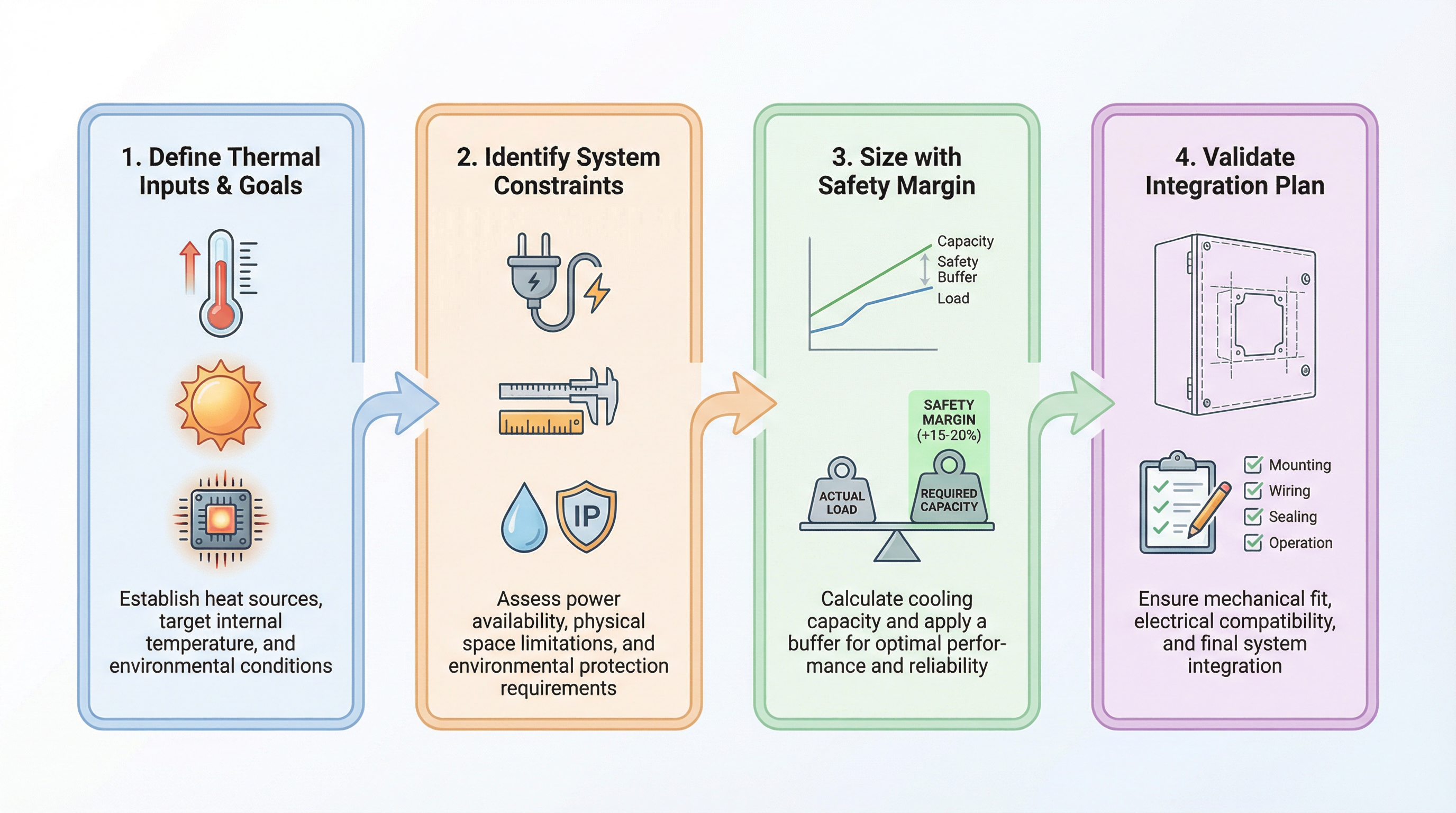
A 4-Step Framework for Sizing and Selection
Selecting the right micro dc air conditioner for sealed enclosures is a systematic process. Rushing this step by under-sizing the unit is a common cause of failure. Follow this engineering-led approach.
Step 1: Define Thermal Inputs and Goals
The foundation of any thermal design is a thorough heat load calculation. This requires quantifying all sources of heat.
- Internal Heat Load (Q_internal): Sum the maximum power dissipation (in watts) of all components inside the enclosure. This data is typically found on component datasheets. For a power supply, for instance, if it is 90% efficient and drawing 500W, it is dissipating 50W as heat.
- External Heat Transfer (Q_external): Calculate the heat transfer through the walls of the enclosure due to the temperature difference between the ambient air and the desired internal temperature. This depends on the enclosure’s surface area, construction material (thermal conductivity), and insulation.
- Solar Load: If the enclosure is outdoors and exposed to direct sunlight, the solar radiation adds a significant heat load, which must be factored in. This varies by location, color, and surface finish.
- Set a Target Temperature (T_internal): Define the maximum allowable internal temperature to ensure component reliability, typically around 25-35°C.
The total cooling requirement is Q_total = Q_internal + Q_external + Q_solar.
Step 2: Identify System Constraints
With the thermal load defined, overlay the physical and electrical constraints of the project.
- Power System: What is the available DC voltage (12V, 24V, 48V)? What is the maximum current the power supply can allocate to the cooling unit?
- Physical Space: What is the maximum height, width, and depth available for the cooling unit? Where can it be mounted (door, side wall, top)?
- Environment: What is the maximum expected ambient temperature? What level of dust and moisture protection (NEMA or IP rating) is required?
Step 3: Size the Unit with a Safety Margin
Using the calculated Q_total, consult manufacturer performance charts. Find a unit whose cooling capacity curve is above your Q_total at the maximum expected ambient temperature. Do not use the nominal capacity rating, as this is often measured at a lower ambient temperature. It is standard practice to add a safety margin of 20-25% to the calculated heat load to account for unforeseen factors like component aging, dust accumulation on coils, and brief periods of extreme temperatures.
Step 4: Validate the Integration Plan
The final step is to ensure the chosen unit can be implemented correctly. Review the mechanical drawings to confirm the cutout dimensions and mounting pattern. Plan the electrical wiring, ensuring proper wire gauge and circuit protection. Critically, plan for condensate drainage. Does the unit have an integrated evaporator, or does it require a drain tube routed to the exterior of the enclosure?
Implementation Checklist for System Integrators
Proper installation is just as critical as proper selection. A perfectly sized unit can fail if installed incorrectly.
- Mechanical Installation
- Verify the enclosure panel is strong enough to support the unit’s weight.
- Use the provided template to make precise cutouts. Burrs and sharp edges should be filed smooth to prevent damage to the sealing gasket.
- Install the sealing gasket correctly between the unit and the enclosure wall. Ensure it is continuous and not twisted.
- Tighten all mounting fasteners to the manufacturer’s recommended torque specification in a star pattern to ensure even compression of the gasket.
- Electrical Connection
- Use wiring of a sufficient gauge to handle the unit’s maximum current draw without significant voltage drop.
- Connect the power supply with the correct polarity. Reverse polarity can damage the control electronics.
- Ensure the DC power source is stable and filtered. Noisy power can affect the controller and compressor performance.
- Connect any alarm or remote control wiring as specified in the manual.
- Thermal and Airflow Management
- Ensure there is sufficient clearance around the external (condenser) air intake and exhaust vents. Blocking airflow will dramatically reduce cooling performance.
- Inside the enclosure, arrange components and wiring to avoid obstructing the cool air outlet or the warm air return of the unit. Promoting good internal air circulation is key.
- Commissioning and Maintenance
- After installation, power on the unit and allow the system to stabilize. Verify that the internal temperature reaches and maintains the desired setpoint.
- Check that the condensate management system is functioning correctly and there are no leaks.
- Establish a periodic maintenance schedule. This should include inspecting and cleaning the external condenser coil to remove any accumulated dust or debris that could impede airflow.

Frequently Asked Questions (FAQ)
1. What is a micro DC air conditioner and how is it different from a Peltier cooler?
A micro DC air conditioner is a miniaturized vapor-compression refrigeration system that uses a compressor and refrigerant to move heat. A Peltier (thermoelectric) cooler uses a solid-state semiconductor junction to move heat. The key difference is efficiency; vapor-compression systems have a much higher COP, meaning they provide more cooling per watt of electricity consumed, making them superior for medium to high heat loads.
2. Can I use a micro DC air conditioner to cool below the ambient temperature?
Yes. This is a primary advantage of an active, refrigerant-based system. Unlike a simple fan or heat exchanger that can only keep the internal temperature above ambient, a DC air conditioner can actively pump heat out of the enclosure to achieve an internal temperature that is significantly lower than the outside air.
3. How do I accurately calculate the total heat load for my enclosure?
A precise calculation involves summing the heat dissipation (in watts) of all internal components and adding the heat transfer through the enclosure walls. For a quick estimate of heat transfer, you can use the formula: Q (Watts) = U * A * ΔT, where A is the surface area, ΔT is the temperature difference, and U is the overall heat transfer coefficient of the enclosure material. For critical applications, using online calculators or consulting with a thermal engineer is recommended.
4. What is the significance of the “closed-loop” design?
The closed-loop design is critical for sealed enclosures. It uses two separate air paths: one circulates and cools the air inside the enclosure, while the other uses outside air to reject heat. This allows heat to be removed without ever mixing the clean internal air with the potentially dirty, humid, or corrosive ambient air, thus maintaining the enclosure’s NEMA or IP rating.
5. What DC voltages are typically available for these units?
Micro DC air conditioners are designed for native DC power systems. The most common voltage options are 12V, 24V, and 48V DC, which align with standard power supplies in industrial automation, telecommunications, and battery-powered mobile applications.
6. How does humidity inside the enclosure affect the system?
The cooling process naturally dehumidifies the air. As warm, moist internal air passes over the cold evaporator coil, water vapor condenses into liquid. This is beneficial as it protects electronics from moisture, but the liquid condensate must be managed. Units typically incorporate a drain port or a condensate evaporator to remove this water.
7. Is professional installation required?
While the units are designed for integration by system engineers and technicians, proper installation is crucial for performance and sealing. Anyone performing the installation must follow the manufacturer’s instructions precisely, especially regarding the cutout dimensions, gasket placement, and fastener torque, to ensure a perfect seal is achieved.
8. What is the typical service life of a miniature DC compressor?
Miniature DC compressors are highly engineered components designed for long life and reliability. Service life depends on the application, duty cycle, and operating conditions, but they are generally designed for tens of thousands of hours of continuous operation, making them suitable for mission-critical systems like those found in telecom components cooling.
Conclusion: The Right Tool for a Demanding Job
The challenge of cooling sealed electronics enclosures is a direct consequence of the need for reliability in harsh environments. A micro DC air conditioner provides an elegant and effective solution by addressing the dual requirements of heat removal and environmental isolation. By employing an efficient, closed-loop vapor-compression cycle, these systems can handle significant heat loads, maintain a stable internal environment below ambient temperatures, and operate on native DC power—all while preserving the integrity of the enclosure’s seal.
For OEM engineers and system integrators, the decision to use this technology is a strategic one. It is the best-fit solution when passive cooling is insufficient, when thermoelectric coolers are inefficient, and when reliability cannot be compromised. Following a structured approach to calculating heat loads, identifying constraints, and planning for integration ensures that the chosen thermal management system will protect your critical electronics for years to come.
Properly sizing and selecting a cooling solution is critical to system success. If you are designing a system with a sealed enclosure that requires active thermal management, contact our engineering team to discuss your specific project requirements and validate your selection.