
Understanding and Solving Sealed Enclosure Overheating
As an engineer designing or integrating systems within sealed enclosures, you’ve likely encountered a frustrating thermal paradox. The internal temperature of a critical control cabinet is climbing, threatening sensitive variable frequency drives (VFDs), PLCs, or power supplies. The instinctive, seemingly logical first step is to increase airflow by installing a larger, more powerful fan. Yet, after the modification, the temperature barely drops—or in some cases, it even increases. This is a common and costly engineering pitfall rooted in a misunderstanding of heat transfer within a closed system. The problem isn’t insufficient airflow; it’s a lack of a pathway for heat to exit the system entirely.
This article provides a data-driven analysis of why the “bigger fan” approach fails for sealed systems and presents a systematic framework for correctly diagnosing and solving the core issue of sealed enclosure overheating. By the end, you will be equipped to move beyond ineffective remedies and select a robust, reliable cooling solution that protects your critical components, preserves your enclosure’s environmental rating, and ensures long-term system stability. We will explore the fundamental principles of closed-loop cooling and outline a practical, four-step process for sizing and implementing an appropriate thermal management system.
Get A Sample Online
Product Link: https://rigidchill.com/3.8cc-twin-cylinder-micro-dc-aircon


Context: Where Sealed Enclosures Face Thermal Threats
The challenge of cooling a sealed cabinet is not a niche problem; it’s a critical design constraint in numerous demanding industries. The need to isolate sensitive electronics from the surrounding environment is non-negotiable, but this very isolation creates a thermal trap. Two common scenarios highlight this challenge:
- Industrial Automation and Control Panels: On a factory floor, control cabinets for robotics, CNC machines, and process automation are constantly exposed to airborne contaminants. Metallic dust, oil mist, corrosive chemicals, and high-pressure washdowns necessitate enclosures with high NEMA or IP ratings. These sealed boxes protect expensive VFDs, controllers, and communication modules, but the heat generated by these same components has nowhere to go. A simple fan would only circulate the hot, contaminated factory air, defeating the purpose of the seal.
- Telecommunications and Edge Computing: Roadside cabinets for 5G infrastructure, remote monitoring stations, and edge data processing must withstand extreme weather conditions. They are sealed to protect against rain, snow, dust, and humidity. These enclosures face a double thermal threat: significant internal heat load from power amplifiers and servers, compounded by external solar gain from direct sunlight. In this environment, enclosure cooling without airflow from the outside is the only way to maintain operational temperatures without compromising the integrity of the seal.

Failure Modes: Why Conventional Cooling Is Ineffective
Before specifying a solution, it’s crucial to understand why simplistic approaches fail. Relying on passive dissipation or basic fans in a sealed system leads to predictable and damaging outcomes.
- The Convection Trap: This is the primary reason the ‘bigger fan not working sealed cabinet’ problem occurs. A fan inside a sealed box is excellent at one thing: creating convection. It moves air from hotter components to the cooler inner walls of the enclosure, helping to equalize the internal temperature. However, it does not remove any heat energy from the enclosure. The total thermal load remains trapped, and the fan motor itself adds a small amount of additional heat. You are simply stirring hot air in a hot box.
- Exceeding Passive Dissipation Limits: Every enclosure has a maximum rate at which it can passively dissipate heat through its walls to the ambient environment. This rate is governed by the enclosure’s surface area, material, and the temperature difference between the inside and outside. Once the internal heat generation surpasses this limit, the internal temperature will continue to rise until a component fails or a thermal shutdown occurs.
- The Ambient Temperature Ceiling: Passive cooling and even air-to-air heat exchangers rely on a favorable temperature differential. If the external ambient temperature is already high (e.g., 40°C), it becomes nearly impossible for an enclosure to passively cool its internal components to a safe operating temperature (e.g., 45°C).
- Breaking the Seal: The most dangerous ‘solution’ is to cut vents or louvers and install an exhaust fan. While this does remove hot air, it completely compromises the enclosure’s NEMA/IP rating. This action immediately exposes sensitive electronics to the very dust, moisture, and corrosive elements the enclosure was designed to block, leading to premature and often catastrophic failure.
- Power and Space Constraints: These systems often run on specific DC voltages (12V, 24V, 48V) and have limited physical space for bulky cooling equipment, ruling out many traditional AC-powered solutions.
Engineering Fundamentals: The Power of Closed-Loop Air Conditioning
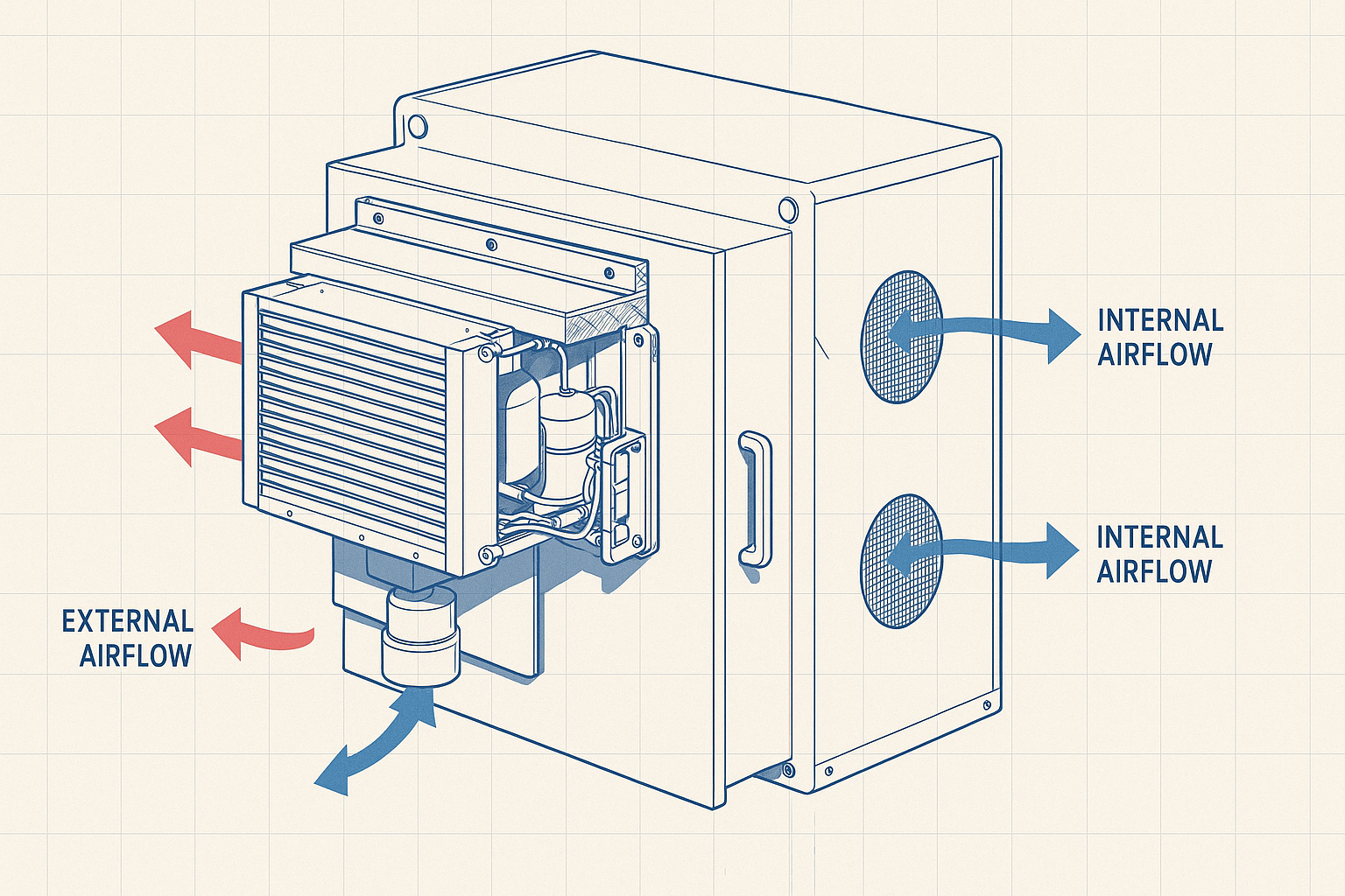
The correct approach to solving sealed enclosure overheating is to create a pathway for heat to escape without compromising the seal. This is achieved through a closed-loop cooling system, such as a compact DC air conditioner. This technology operates on two independent airflow principles.
The Two Critical Air Loops
1. The Internal (Cold) Loop: A fan located within the cooling unit circulates air exclusively *inside* the sealed enclosure. This air is drawn over the hot electronic components, where it absorbs their waste heat. The now-warm air is then directed across the cooling unit’s evaporator coil. Here, the heat is transferred from the air to a cold refrigerant, causing the air to cool down before it is recirculated back into the enclosure. This continuous cycle actively removes heat from the components.
2. The External (Hot) Loop: A second, completely separate fan draws air from the *ambient environment* outside the enclosure. This external air is passed over the unit’s condenser coil. The heat that was absorbed by the refrigerant in the internal loop is transferred to this external airflow and exhausted back into the atmosphere. The refrigerant then cycles back to the evaporator to pick up more heat.
The cooling unit itself is mounted through the wall of the enclosure, forming a thermal barrier. A gasket ensures the NEMA/IP seal is maintained, so no air is ever exchanged between the inside and outside. This is the essence of effective enclosure cooling: heat is actively pumped out, while the protected internal environment remains pristine.

The Vapor-Compression Advantage
Unlike a simple heat exchanger, which can only cool the inside to a temperature slightly above the outside ambient, a vapor-compression system like a Micro DC Aircon can actively cool the enclosure to temperatures below ambient. This is critical for applications in hot climates or with high solar load, where maintaining a safe operational temperature would otherwise be impossible.
Key Specifications for Sealed Enclosure Cooling Solutions
When evaluating active cooling units, focusing on the right performance metrics is essential. While specific values vary by model, these are the critical parameters to consider for any compact, refrigerant-based system:
- Cooling Capacity (Watts): This is the rate at which the unit can remove heat. It must be greater than the total heat load of your enclosure. It’s important to note that this capacity is not constant; it derates (decreases) as the ambient temperature rises. Always check performance data for the unit’s capacity at your maximum expected operating temperature.
- Input Voltage (VDC): The unit must be compatible with the DC power available in the cabinet. Common options include 12V, 24V, and 48V, which are standard in telecommunications, off-grid, and industrial control systems.
- Operating Temperature Range: This defines the minimum and maximum ambient temperatures in which the unit can function reliably. Ensure your hottest environmental conditions fall within this range.
- Physical Dimensions and Mounting: The unit’s footprint, depth, and mounting configuration (e.g., side, door, or top-mounted) must fit the physical constraints of your enclosure without obstructing access or internal components.
- Environmental Sealing (NEMA/IP Rating): The cooling unit must be designed with appropriate gasketing and construction to maintain the enclosure’s required environmental rating after installation. This ensures continued protection against dust and moisture.
- Control and Efficiency: Modern systems use BLDC inverter compressors and variable-speed fans. This allows the cooling output to be precisely matched to the thermal load, significantly improving energy efficiency and reducing component wear compared to simple on/off systems.
A 4-Step Framework for Sizing and Selection
Follow this systematic process to ensure you choose a cooling solution that is both effective and efficient, preventing the common problem of sealed enclosure overheating.
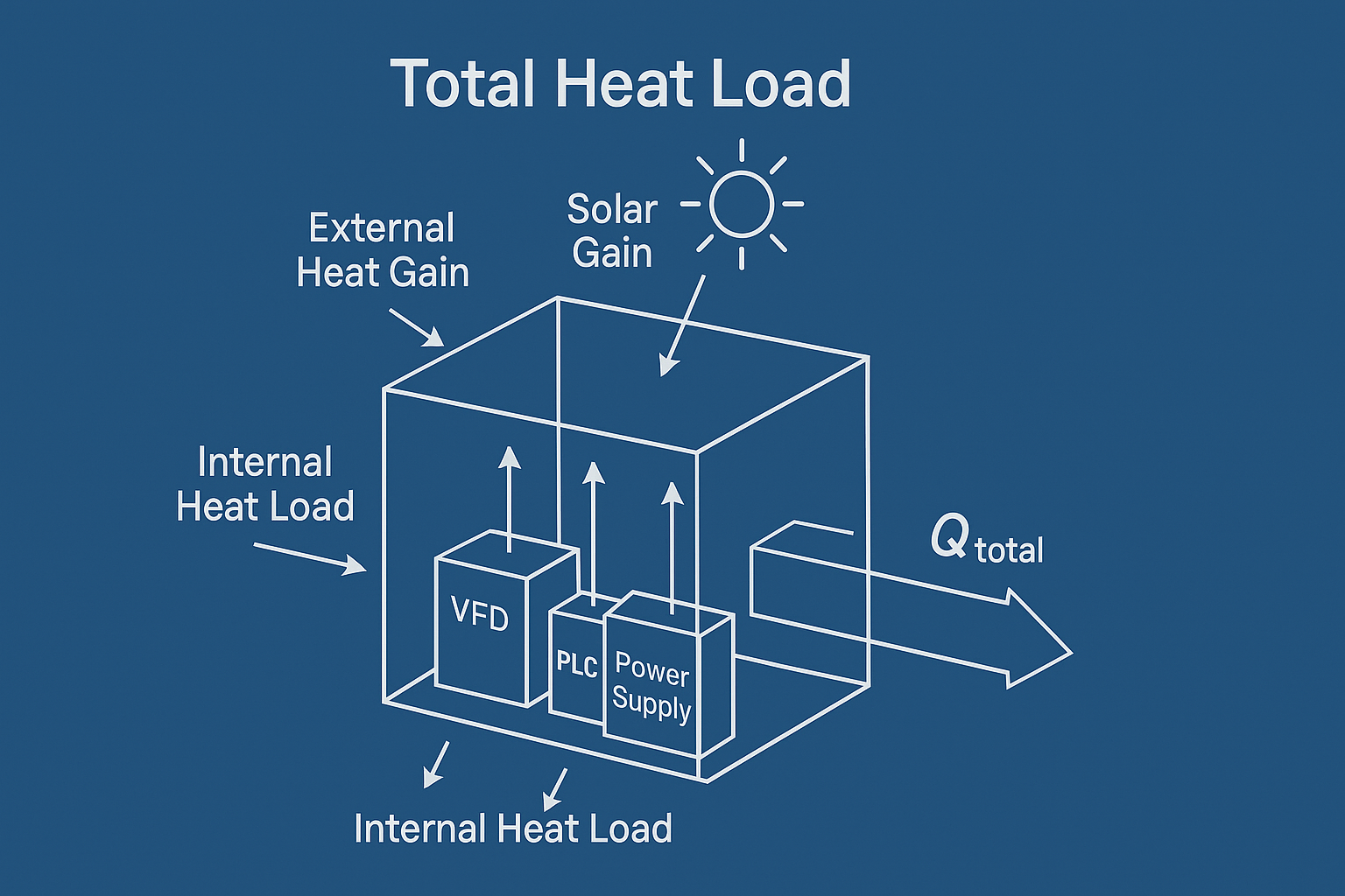
Step 1: Calculate Your Total Heat Load (Q_total)
Your total heat load is the sum of all heat sources. Be thorough in this step.
- Internal Heat Load: Sum the maximum power consumption (in watts) of all active components inside the enclosure. For devices like VFDs and power supplies, check datasheets for heat dissipation values. If not available, a conservative estimate is that 80-95% of power consumed is converted to heat.
- External Heat Load (Heat Gain): Calculate the heat transferred into the enclosure from the outside. This depends on the enclosure’s surface area, construction material, insulation, and the maximum temperature difference between the desired internal temperature and the peak ambient temperature. For outdoor units, solar gain from direct sunlight is a major factor and must be added to the calculation.
Step 2: Define Your Operating Constraints
List the non-negotiable parameters of your application.
- Maximum Allowable Internal Temperature: Determined by the most thermally sensitive component in your system.
- Maximum and Minimum Ambient Temperature: The real-world environmental conditions the enclosure will experience.
- Available Power: The specific DC voltage (12V, 24V, 48V) and the maximum current the power supply can provide.
- Physical and Environmental Requirements: The required NEMA/IP rating and any space or mounting limitations.
Step 3: Select the Appropriate Cooling Technology
Based on your heat load and constraints, choose the right class of solution. For any sealed enclosure where the internal heat load is significant or the ambient temperature can approach or exceed the desired internal temperature, a vapor-compression system like a Micro DC Air Conditioner is the most reliable choice. It is the only common technology that can actively pump heat out against a thermal gradient.
Step 4: Validate and Apply a Safety Margin
Never size a unit for the bare minimum.
- Add a Safety Factor: Select a cooling unit with a nominal cooling capacity that is at least 20-25% higher than your calculated total heat load. This accounts for potential future equipment additions, component aging, and unforeseen inefficiencies.
- Check Derating Curves: Consult the manufacturer’s performance charts. Find your maximum ambient operating temperature on the chart and verify that the unit’s *derated* cooling capacity at that temperature still exceeds your total heat load plus the safety margin. This is the most critical validation step.
Implementation Checklist: Best Practices for Installation
Proper installation is just as important as proper selection. A poorly installed unit will underperform and can compromise the enclosure’s integrity.
- Mechanical Integration
- Ensure the mounting surface is flat, rigid, and can support the weight of the cooling unit.
- Use the provided template to make precise cutouts. Burrs and sharp edges should be filed smooth to prevent gasket damage.
- Install all gaskets correctly and tighten mounting hardware evenly to the recommended torque to create a perfect seal.
- Verify that the external condenser has several inches of clearance for unobstructed airflow. Do not install where the hot exhaust air can be immediately drawn back into the intake.
- Electrical Connection
- Use wiring of the appropriate gauge to handle the unit’s maximum current draw without significant voltage drop.
- Connect to a stable, regulated DC power supply that meets the unit’s specifications.
- Properly ground the unit according to local electrical codes and manufacturer instructions.
- Thermal Configuration
- Position the cooling unit so its internal cold air discharge creates a convection pattern that flows over the hottest components first.
- Ensure internal cables and hardware do not block the unit’s air intake or outlet.
- If the unit has a condensate drain, ensure the tube is routed with a continuous downward slope and is not kinked or blocked.
- Commissioning and Maintenance
- After installation, power on the unit and let it run for a full cycle to confirm it cools to the setpoint and operates smoothly.
- Establish a simple maintenance schedule. The most important task is to periodically inspect and clean the external condenser coils. Clogged coils are the number one cause of reduced cooling performance.
Frequently Asked Questions (FAQ)
1. Why can’t I just use a thermoelectric (Peltier) cooler?
Thermoelectric coolers can be effective for very small heat loads, but they are significantly less efficient (lower COP) than vapor-compression systems. For heat loads over 100-150W, a DC air conditioner is typically a more energy-efficient and powerful solution.
2. What is the difference between an air-to-air heat exchanger and a DC air conditioner?
A heat exchanger uses the temperature difference between the inside and outside to transfer heat. It cannot cool the internal temperature below the external ambient temperature. An air conditioner uses a refrigerant cycle to actively pump heat out, allowing it to cool the enclosure to well below the ambient temperature.
3. How do I accurately calculate the heat load from my components?
The best source is the component’s technical datasheet, which often lists heat dissipation in Watts or BTU/hr. If not available, you can approximate it from the power consumption, assuming most electricity that doesn’t perform mechanical work becomes heat.
4. Do compact DC air conditioners consume a lot of power?
Modern units featuring variable-speed BLDC inverter compressors are highly efficient. They modulate their speed to match the cooling demand, consuming significantly less power than older, fixed-speed designs, especially under partial load conditions.
5. How does solar radiation affect cooling needs for an outdoor cabinet?
Direct sunlight adds a significant external heat load that must be included in your total calculation. The amount depends on the cabinet’s color, surface area, and geographic location. Using a solar shield or painting the enclosure a light, reflective color can help mitigate this effect.
6. Is a bigger fan ever the right answer for sealed enclosure overheating?
For a truly sealed enclosure, no. A bigger internal fan will only circulate the trapped hot air more quickly. The fundamental problem is the lack of a mechanism to remove heat energy from the sealed volume. The solution must involve transferring heat to the outside world.
7. What is the typical maintenance for a micro DC air conditioner?
Maintenance is minimal. The primary task is periodically cleaning the fins of the external (condenser) coil. Dust, leaves, or other debris can clog these fins and obstruct airflow, which severely reduces the unit’s ability to reject heat.
The Right Approach to Thermal Reliability
The impulse to fight sealed enclosure overheating with a bigger fan is understandable but ultimately flawed. It addresses a symptom (poor convection) instead of the root cause (trapped heat energy). By understanding that a sealed system requires an active, closed-loop mechanism to export heat, you can avoid wasted effort and prevent costly equipment failures.
A systematic approach—calculating the total heat load, defining constraints, selecting the right technology, and validating performance with a safety margin—is the engineering standard for achieving thermal stability. For demanding industrial and telecom components cooling applications, a compact, efficient Micro DC Aircon provides a robust solution that removes heat effectively while preserving the critical environmental seal of your enclosure.
Customized Solutions for Unique Challenges
We recognize that not all applications fit standard parameters. Many projects involve unique voltage requirements, extreme temperature ranges, or severe space constraints. Rigid’s engineering team specializes in developing customized and semi-customized cooling solutions tailored to specific OEM needs. If you are facing a complex thermal management challenge, we encourage you to contact our team to discuss your project requirements and explore a purpose-built solution.